1. Purpose
- First experiments with controlling Roomba
2. Components
- iRobot Roomba 880
- Arduino PRO MINI (5V)
- XL4432-SMT 433MHz Transceiver
3. Results - on YouTube
4. Progress Report
4.1. Intro
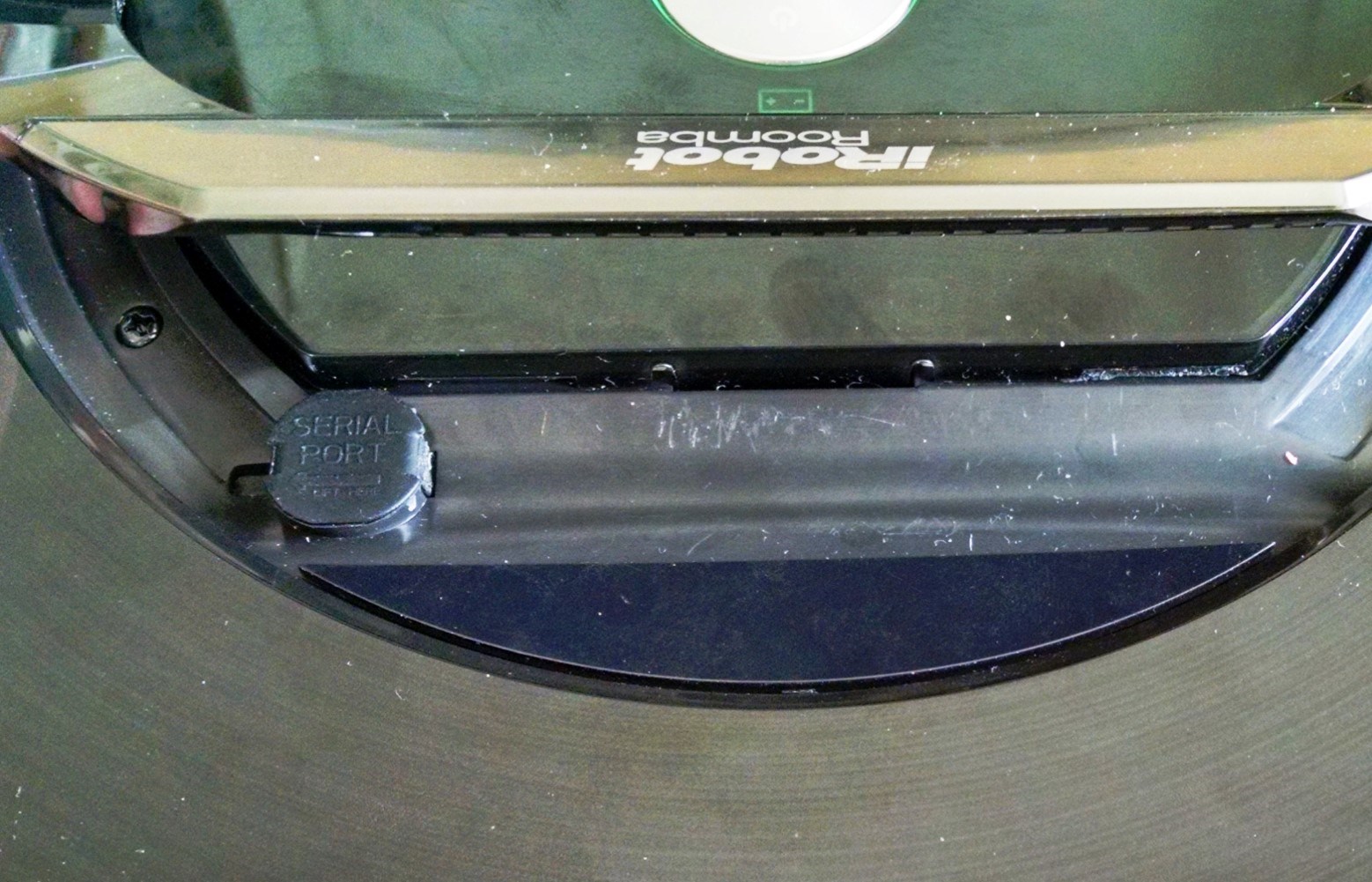
Ever since we got this robot vacuum cleaner for my wife, my hands have been itching to start tinkering with it. I wanted to see what I can do with it. Turns out, guys at iRobot were kind enough to provide an easy way to do just that. Every Roomba has a 7-pin connector, through which one can gain total control over the robot. And it would not even void the manufacturer's warranty! How nice of them!
The connector is located under the handle of my 880. Naturally, my goal was to make a controlling hardware as small as possible, ideally invisible, fitting under this handle. Got to keep in mind the Wife Acceptance Factor!

4.2. Hardware
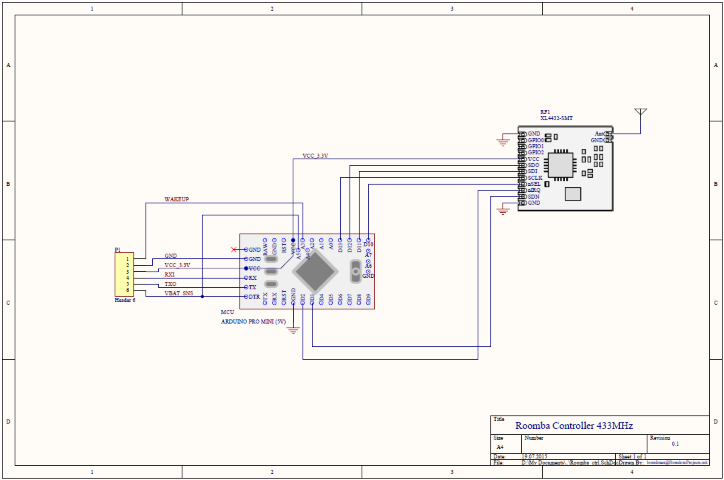
I love Arduino MINI! It is small, simple, exactly what I need, no more, no less. My Arduino Mini is a Chinese made 5V variant, but I needed a 3V type to interface with 3V Radio module. Turns out, the Atmega328P by itself can take any voltage, with restrictions of maximum clock speed. Theoretically, running at 16MHz at 3.3V is outside the specs and is not guarantied. However, I read that other people successfully did it, and it seems to show no problems here. I removed the linear regulator and disconnected LED resistor to save power. Now the Mini gets its power directly from 3.3V VCC connection.
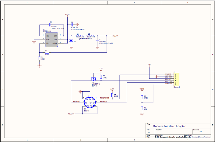
To create the power for Arduino, I built a small efficient switch-mode power supply based on LMR14006 regulator IC from Texas Instruments. The Roomba battery voltage can be as high as 20 volts and I needed a stable 3.3V for controller, while maximizing efficiency. At no load, this regulator consumes only 30µA even at high input voltage.
The logic level shifter between 5V TTL signals of Roomba and 3.3V levels of Arduino is built based on this application note: http://www.irobot.com/~/media/MainSite/PDFs/About/STEM/Create/Create_2_Serial_to_33V_Logic.pdf
I opted for a modular design, where DC-DC power supply and serial port level shifted are built on a separate small board, connecting to Arduino Mini through a 6-pin header connector.
Here are schematics of both parts:
 |
 |
The resistors R5, R6 make a voltage divider that I use to measure Roomba's main battery voltage through an analog input pin.
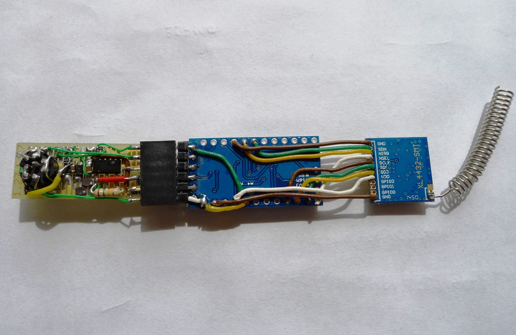
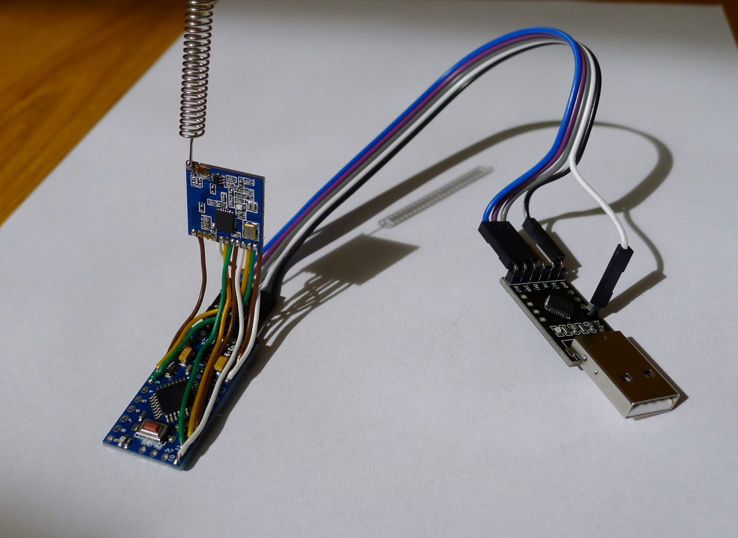
It took some ugly soldering work, but it seems to be successful. Here are some pics:
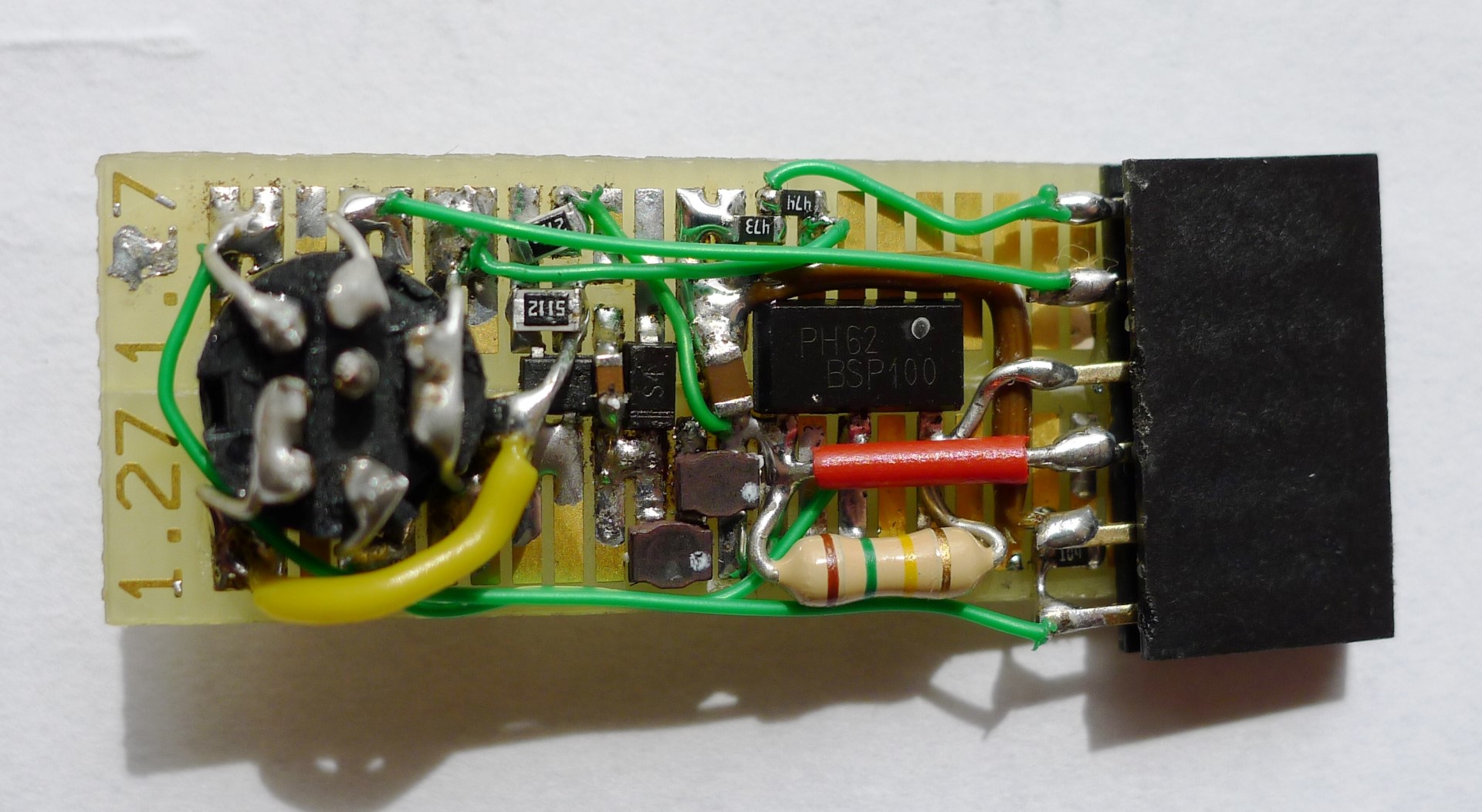 |
 |
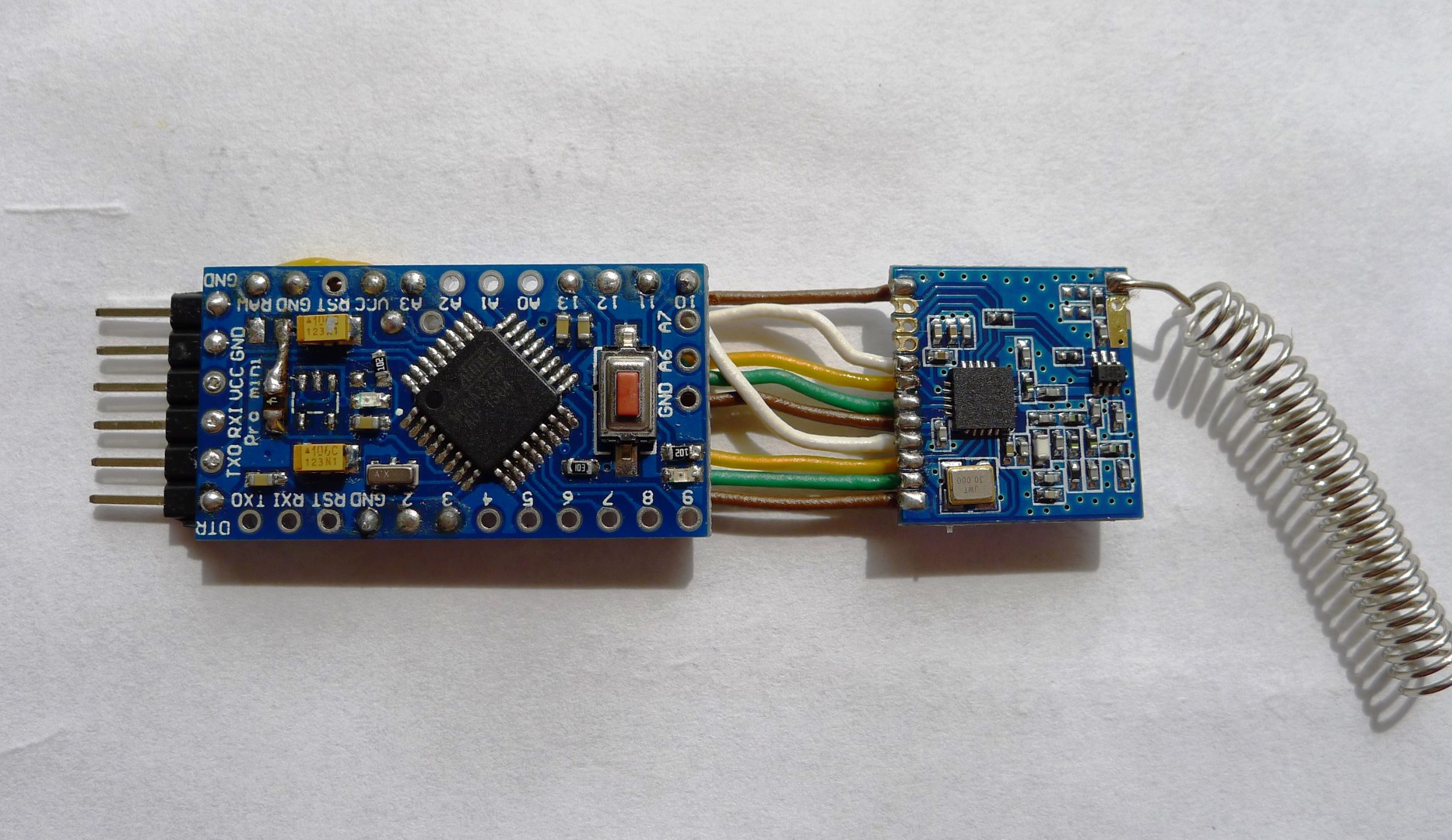 |
 |
|
|
|
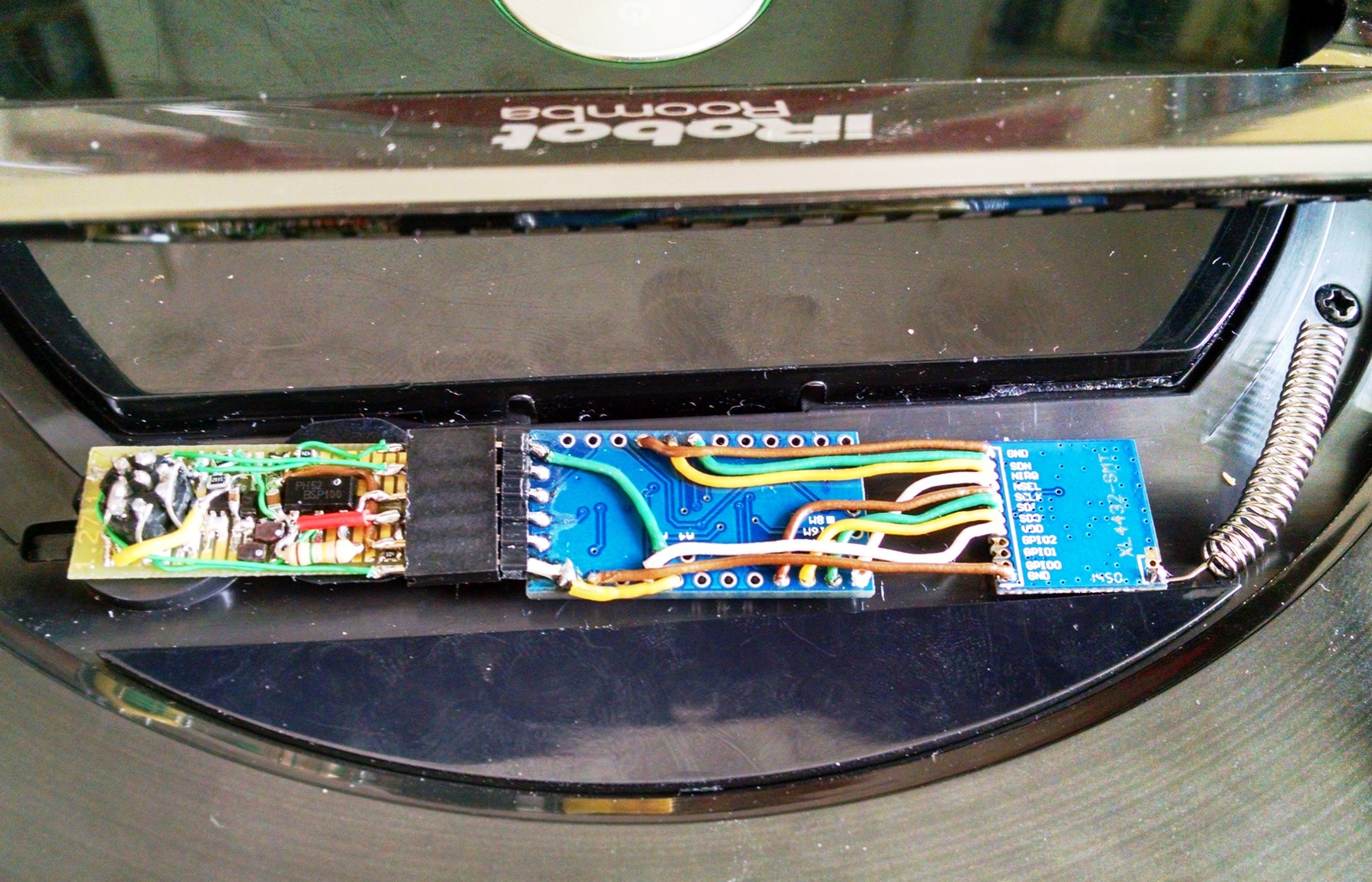
This is how it fits under the handle of Roomba:
 |
 |
4.3. Software
Zipped files: Roomba_sketches.zip
the end :)