1. Purpose
- Prepare a platform for robotic vision and navigation experiments
- Implement all necessary power management and drive controls
- Give Raspberry Pi ability to directly control robot's movements
2. Components
- DFRobot Cherokey 4WD Mobile Platform
- NiMH 2500mAh AA batteries (5pcs)
- Graupner 6425 NiMH charger
- 5V Step-up/down Voltage Regulator S18V20F5
- Raspberry Pi rev.3
- Arduino Pro Mini (ATmega168P clone)
3. Results
4. Progress Report
4.1. Intro
My first experiments with computer vision started with Roomba Autopilot based on Raspberry Pi and OpenCV, where I attempted to implement vehicle location and guiding through an external sensor - Owl, permanently mounted in a remote location. The Owl observes the scene, locates robot within its field of view and remotely controls it through wireless communication. Building upon these experiments, I decided now to move to the real autonomous navigation and guiding functionality, this time built into the robot itself.
First step towards this goal was to build a mobile robotic platform, containing all necessary basic features, such as power source, battery charge/discharge monitoring and mobility controls. The platform must be sturdy enough to carry, when time comes, additional motion/location sensors, such as a camera. It must also have enough spare computing power to be ready for such processing.
I decided to use the four wheeled mobile platform from DFRobot - Cherokey 4WD, because it was easy to use and because it already contained necessary motor driver circuitry.
Choice for the main computer was easy - Raspberry Pi 3.
4.2. Hardware
4.2.1. Concept
The most important part of a robot is its battery, no? The Cherokey platform has a battery holder for 5 AA batteries, so I bought some 2500mAh NiMH rechargeables. So the questions was how to charge those, in a reasonable time. Additionally, I had the following requirements:
- The battery must be permanently installed into the robot. No removing it for recharging and putting it back afterwards.
- The charger should also be part of the robot. The external power source, when attached, should supply the charger as well as Raspberry Pi and other electronics.
- The power for Rapsberry should be strictly regulated to 5V regardless of battery voltage or external supply voltage fluctuations.
Therefore, I envisioned the following power connection scheme:

- When AC adapter is not plugged in, the battery directly supplies the motors and the Pi through step-up/down regulator.
- When the AC adapter is connected, the charger gets activated and starts recharging the battery, while the Pi gets its power from the input, through the top diode.
- Since the input DC voltage is higher than the battery voltage (even when being charged), the bottom diode is reverse-biased, effectively disconnecting the rest of the circuitry from the charger. That is assuming the motors are not being driven.
4.2.2. Charger
The above creates very specific requirements for the charger circuitry. To make this happen, I initially thought of building my own, something like what's described in this application note: AVR450: Battery Charger for SLA, NiCd, NiMH and Li-Ion Batteries. However, that was not the focus of this project, so instead I went for something half-ready made and bought Graupner 6425 NiMH charger. Turned out, it was surprisingly easy to disassemble and modify. Here's how it looks from the inside:
 |
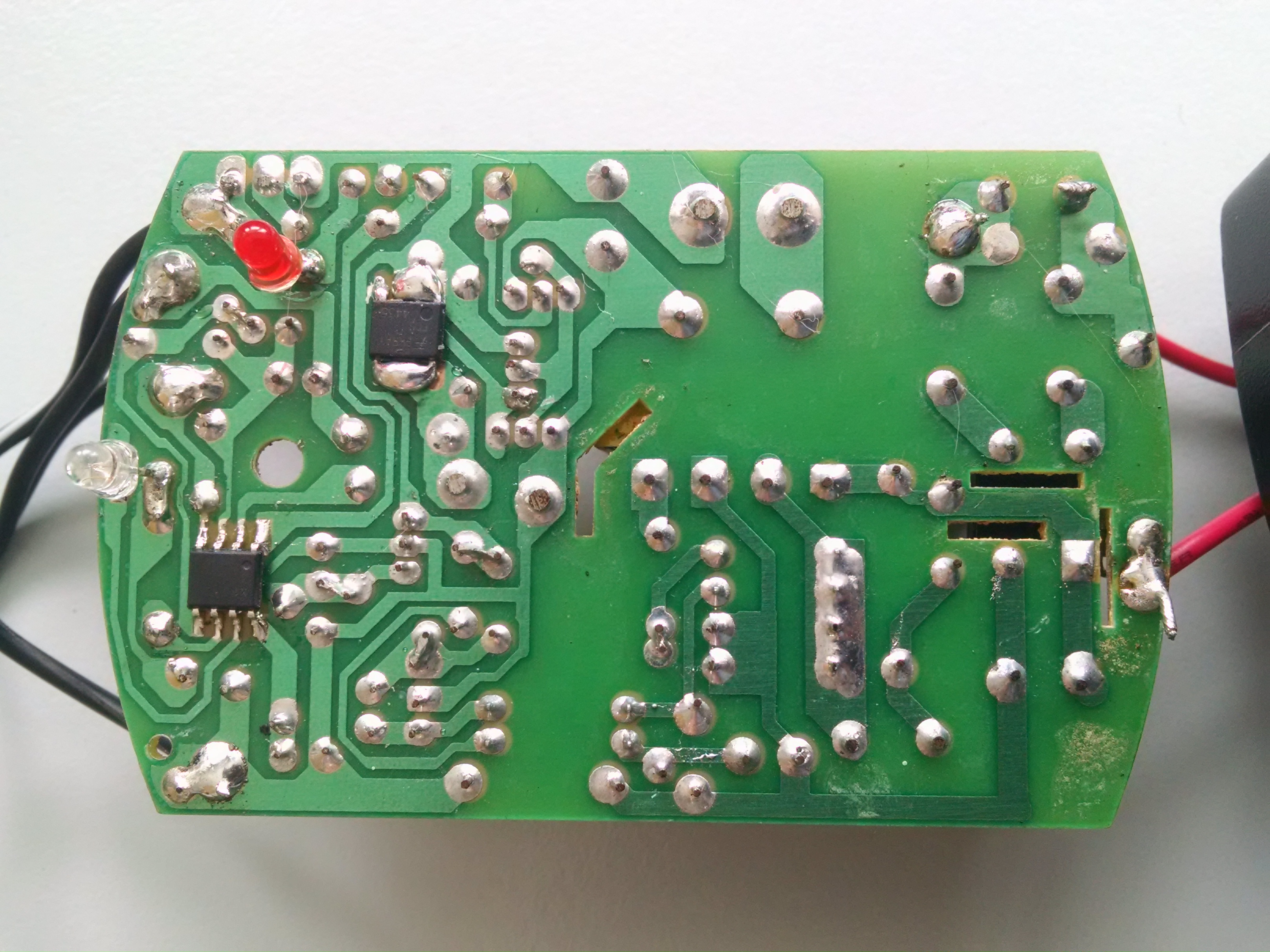 |
and its reverse-engineered schematic diagram:
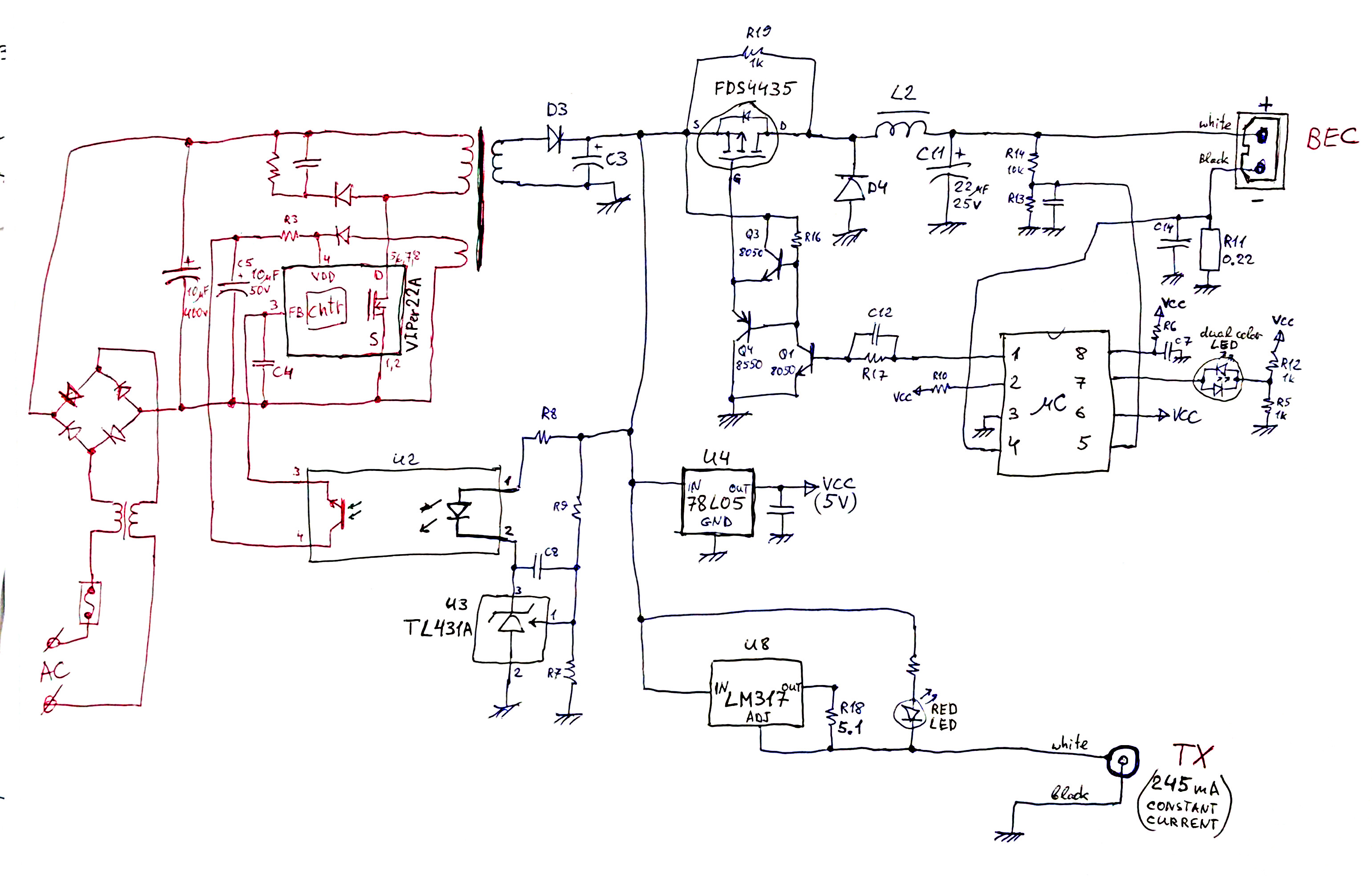
The whole left (red) side of the circuit was disconnected and an external DC supply of about 15V was attached directly to diode D3, replacing secondary transformer winding. In addition, input of U4 - supply regulator for the microcontroller - was moved to the other side of D3, so that the controller becomes powered only when external supply is connected, and not by the battery during its normal discharge.
4.2.3. The Platform
A few pictures of the complete robot assembly:
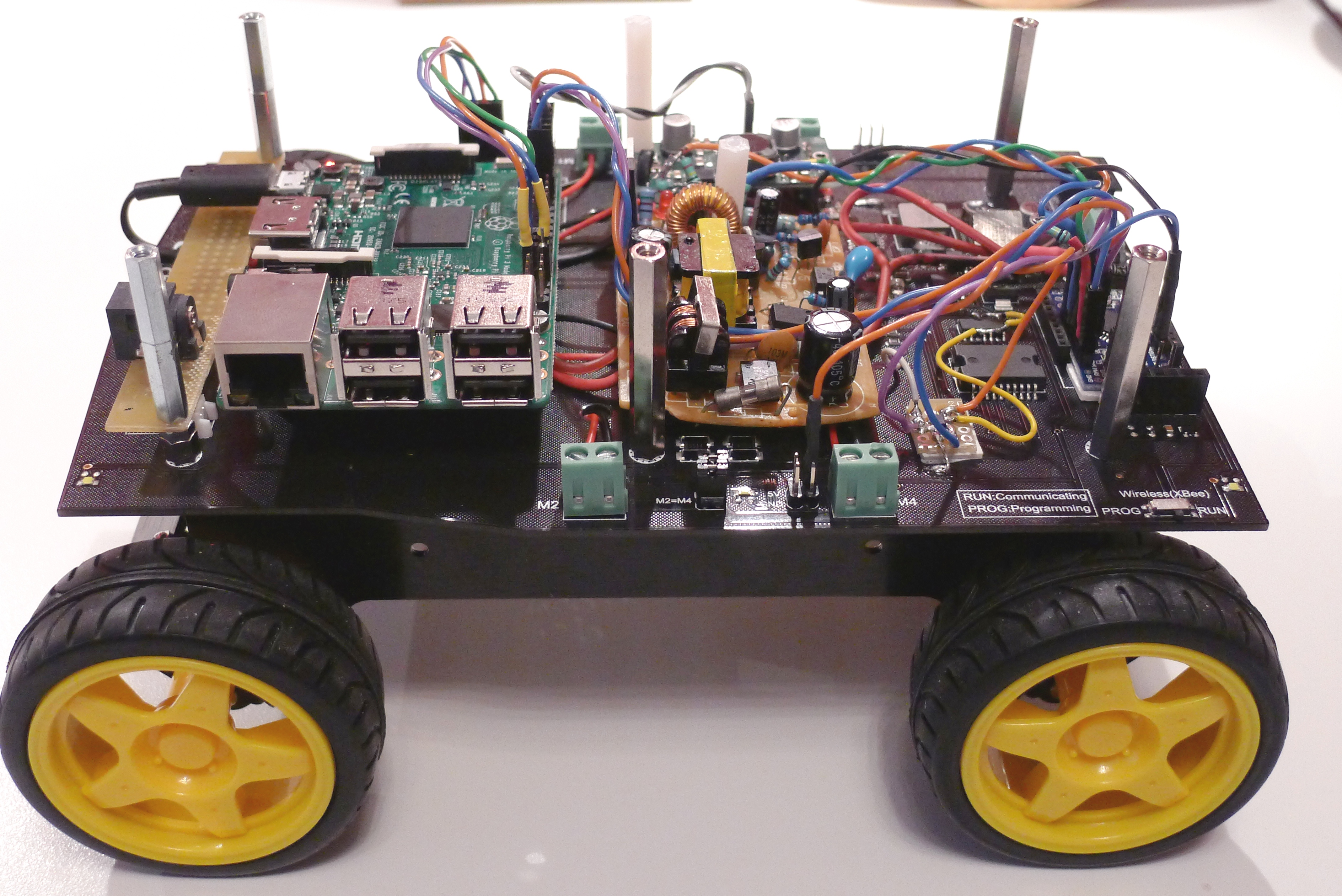 |
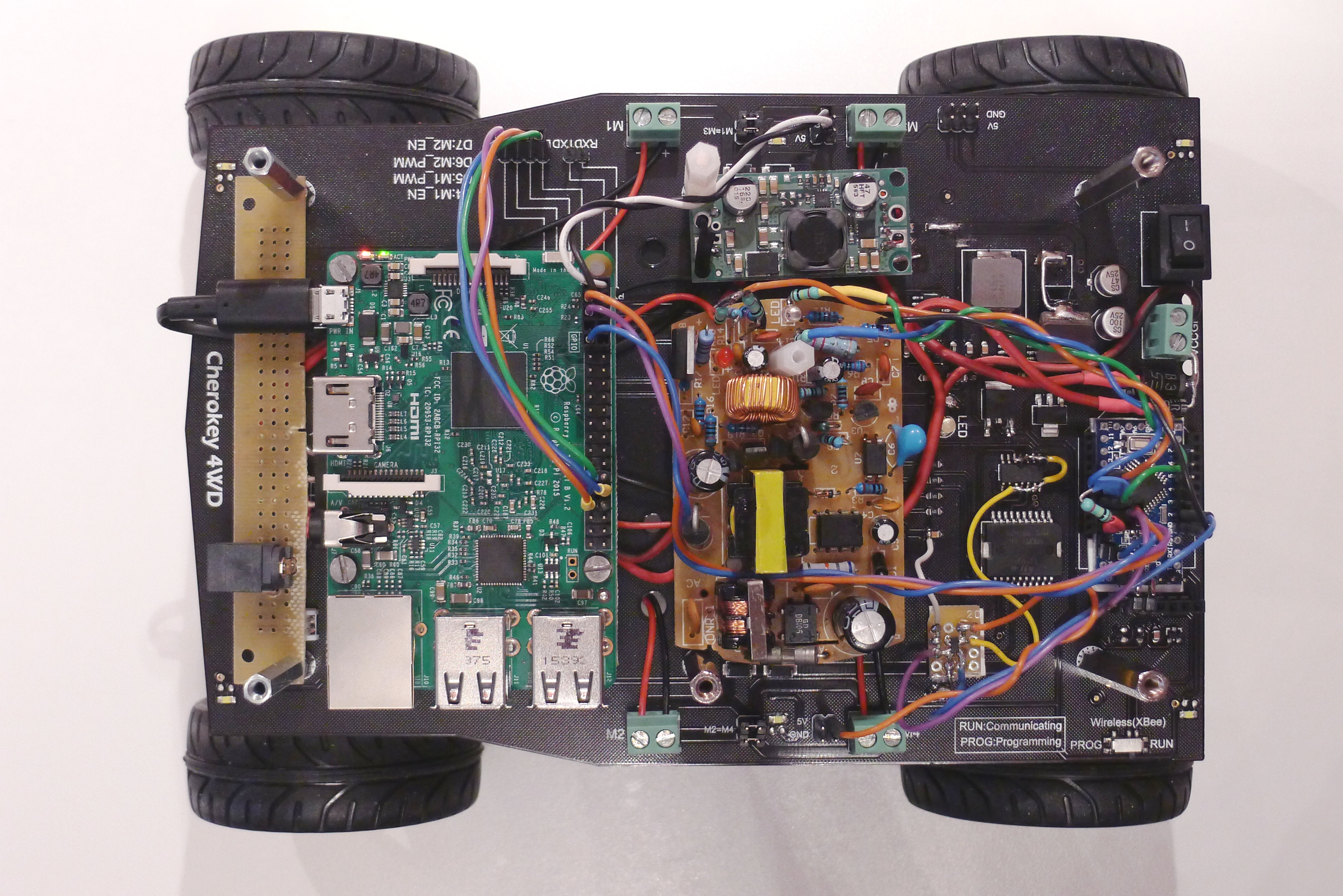 |
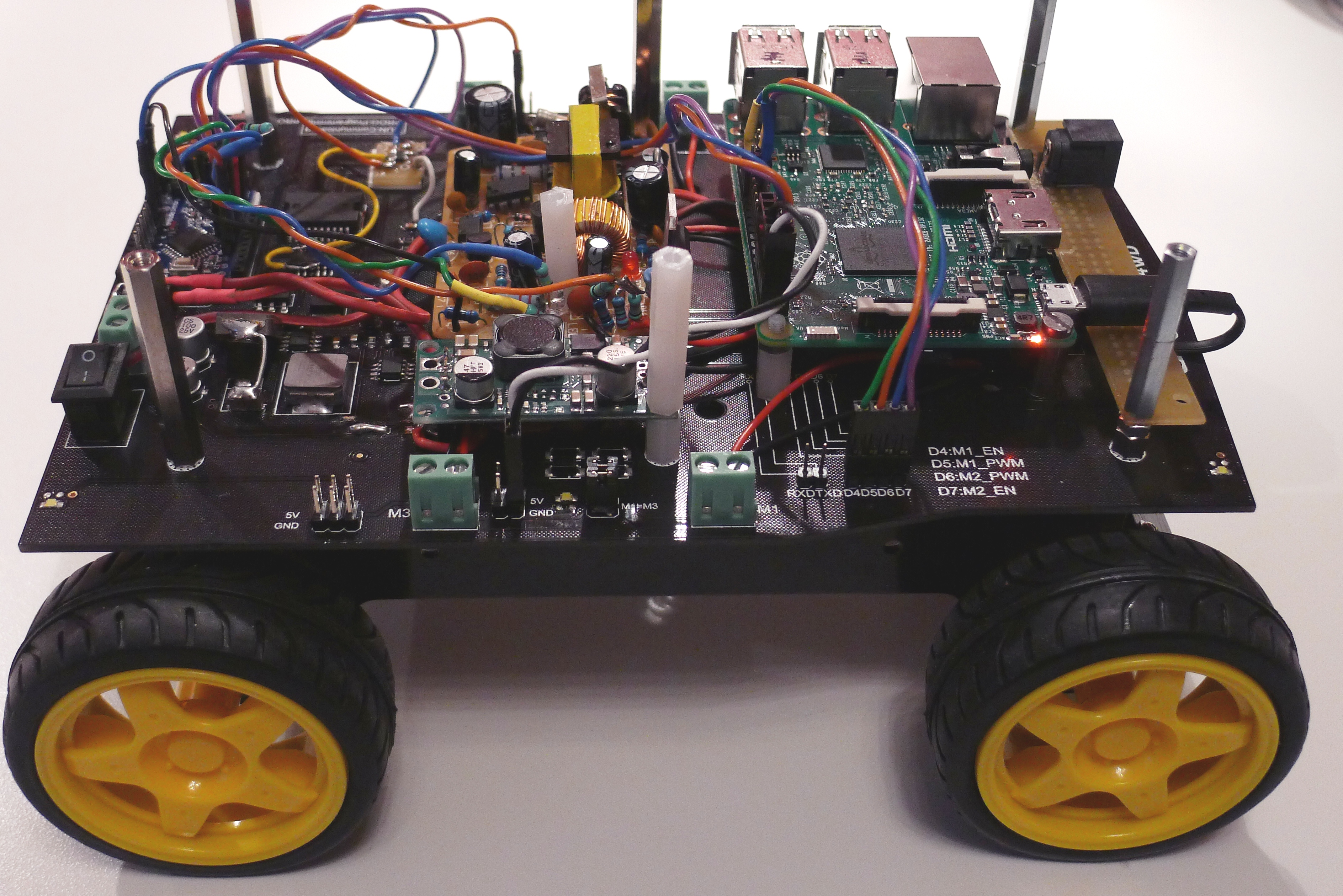 |
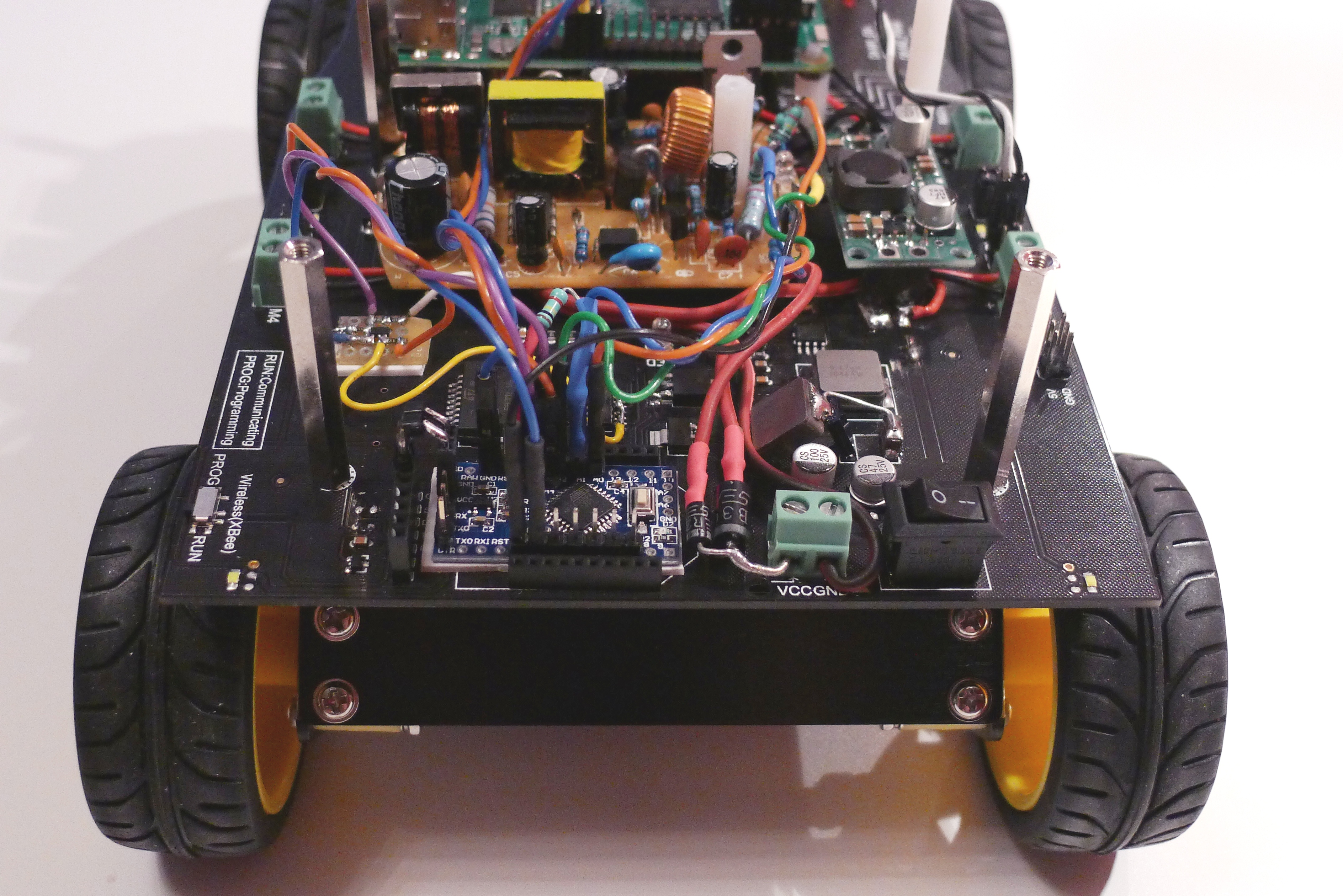 |
as well as its complete connection diagram:
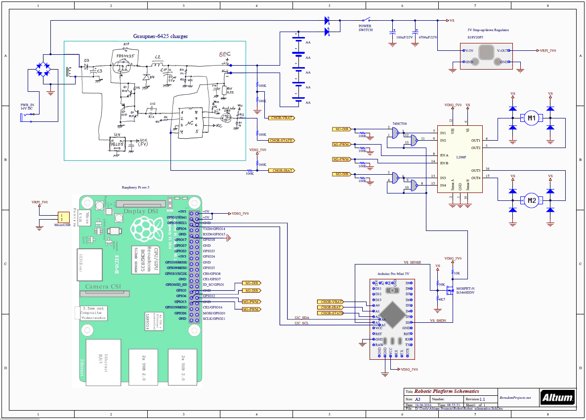
A few notes on the schematics:
My idea was to eventually create a recharging base for the robot, and have it automatically drive onto the base. So, as soon as it attaches itself to the base, the motors should stop running. That is to prevent damage to the motors, since external supply can be as high as 15V. This is accomplished by the N-channel MOSFET (Si3460). To make it happen, Arduino normally maintains a low level on digital output pin D2, while resistor divider (39K and 4.7K) sets the gate voltage. When robot is running on batteries and VS is below 7V, the gate voltage is low and not enough to turn on the MOSFET. Therefore, 10K pull-up resistor on its drain produces a high logic level, allowing motors to run. When supply voltage VS goes up to 15V, the transistor turns on, pulling the drain low, which instantly disables both motors.
Raspberry does have an ability to override this protection mechanism by sending a command to Arduino to remove low level on MOSFET's source pin. Then, motors get re-enabled and Raspberry can carefully apply a low level of PWM to the motors to safely drive the robot out of the charging base.
Two schottky diodes in quadrant A5 provide uninterrupted supply to RPi and the rest of the circuitry, even during charging. When external supply gets connected, the lower diode is reverse-biased, effectively disconnecting battery from everything else, in order to be properly charged.
Supply voltage to Raspberry is regulated by 5V step-up/down converter S18V20F5, regardless of battery voltage or charging state. 5V digital supply to L298 and Arduino is taken from RPi connector.
Analog inputs A0, A1 and A2 are connected to the charger (nets CHGR_VBAT, CHGR_IBAT and CHGR_STATE) to enable continuous monitoring of battery voltage, current and charging status. Input A3 also monitors supply voltage VS.
4.3. Software
The connection between RPi and Arduino was done using I2C bus, based on example from Peter Mount's blog, and the hardware PWM for motor control was implemented using WiringPi library.
4.3.1. Master - Raspberry Pi
After starting the program (as root), arrow keys will control robot's movements and space key will make a hard stop. Hitting 'x' or 'q' will terminate the program.
Direct link: drivetest.cpp
4.3.2. Slave - Arduino
Arduino LED will blink according to the battery voltage level. Lower voltage will produce higher blinking rate, up to a maximum alarm rate of 1/200ms.
Direct link: CherokeySlave.ino