1. The Purpose (Mission)
- Monitor, archive and analyze energy consumption in the house
- Visualize historical consumption data
- Access data remotely from Web
- Eventually include data from other sensors, like temperature, pressure, humidity, motion, light, security, etc.
- UPDATE: Temperature, Pressure and Humidity sensors added: Additional Sensors for Home Energy Monitor
2. Components
- Concept based on OpenEnergyMonitor project
- Hardware based on Arduino and Raspberry Pi platforms
- UPDATE: Raspberry Pi has now been replaced with Ubuntu NAS and Backup Server
- Software: Arduino IDE, EmonLib and RFM12B library by LowPowerLab
3. Progress Report
3.1. Measurement Box
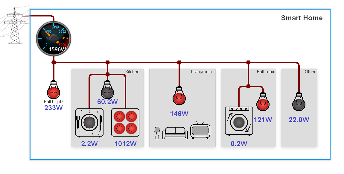
To begin with, I looked at the electrical fuse box in my apartment and noticed that I have 10 or so circuit breakers leading to separate electrical house circuits. I thought that it would be nice to monitor these 10 output lines individually and independently. This way I could have detailed power data as well as compute total house consumption.

When I removed the plastic cover, I noticed that there is quite a lot of space under it, so I hoped I could nicely fit all required hardware inside and hide it from view.
3.1.1. Hardware
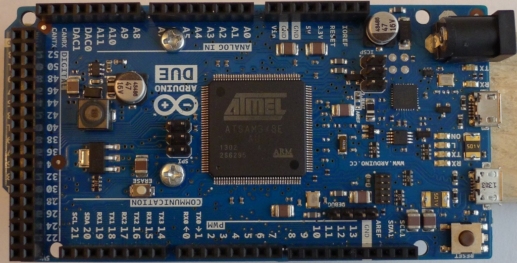
As far as I could see, the original EmonTx approach from OpenEnergyMonitor was to measure current at the input to the breakers. This could be the result of limited measurement speed and/or limited processing power or the Arduino Uno -based hardware. EmonTx has only three current probe inputs with 10-bit resolution. So, instead I decided that I'd need faster processor, more analog inputs and 12-bit ADC resolution. In other words, this Arduino Due board:
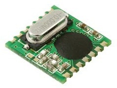
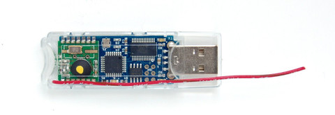
The next logical step was to test wireless communication between this sensor controller and whatever the base might be. For this I purchased a couple of RFM12B modules and a JeeLink from JeeLabs shop:
(NOTE: JeeLink was later replaced with JeeNodeUSB)
|
|
|
3.1.2. RFM12B library for Arduino Due
As a starting point, I used a great port of RFM12B library to C++ by Felix of LowPowerLab.com
Turned out, this library was not compatible with my ARM-based Due board. So I spent the next few weeks on modifying this code and eventually made it to work on my Due. The files are below. Just unzip this into library folder of the Arduino IDE and don't forget to select Due before compiling ;)
https://github.com/icboredman/RFM12B/tree/arduino_due
Not all functionality has been implemented yet, like sleep mode, but overall it does work.
3.1.3. Current / Voltage Sensors
Once I had RF communication working properly between Due and JeeLink, I started working on setting up sensors.
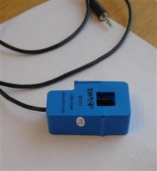
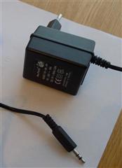
I purchased 12 non-invasive current probes and 1 AC-AC voltage adapter:
 |
 |
Here is a great explanation of Power measurement theory using these sensors.
You can download a complete schematic diagram of my energy monitor here:
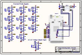
As you can see, I used 22 Ohm burden resistors, which gave me more than enough head room to measure currents up to full range of SCT013 (100A). In addition, to measure line voltage using AC-AC adapter, I adjusted resistive divider to 100K - 6.6K, which slightly reduced resultant voltage range at the Arduino to below 3.3V p-p.
I soldered all components onto this Proto Shield for Arduino MEGA, which also fits perfectly to Due.
UPDATE (Jan. 2016):
Following a suggestion to convert the original crude wire-solder design into something that could be easily duplicated and manufactured, I've taken on Fritzing. I must say, it is a pain-in-the-***. Nevertheless, here's the result, if anybody wants to try it:
http://fritzing.org/projects/emontx-shield-for-arduino-due
Warning, I have not tested this Fritzing design myself, so try at your own risk ;)
In order to utilize full 12-bit ADC resolution of Arduino Due, I reworked original EmonLib library of OpenEnergyProject. Here's my modified source code:
https://github.com/icboredman/EmonLib/tree/feature/12bit_3phase
This mod also contains 3-phase buffer-and-delay algorithm, since my CT inputs are connected to all three line phases, but my AC_AC voltage adapter is connected to only one of them (obviously).
And finally, here's the Arduino sketch that ties this all together:
At the end, after adjusting calibration constants, I was able to see this raw dump of sensor data, occurring every 2 sec:
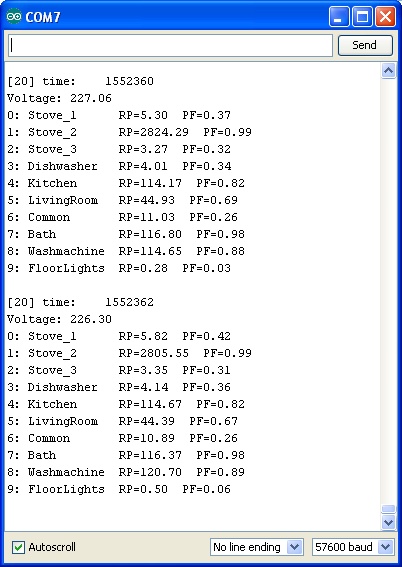
NOTES:
1. The above formatted output was generated using this test sketch EmonRxUno.ino, not to be used in working system.
2. The Arduino sketch for a working RaspberryPi-based system is here: Software
3.1.4. Fitting it all inside my fuse box
Here I will let pictures tell the story...
|
Arduino Due and my EmonTx Shield 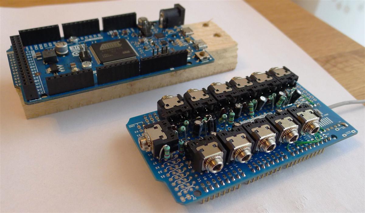 |
|
EmonTx shield - Top 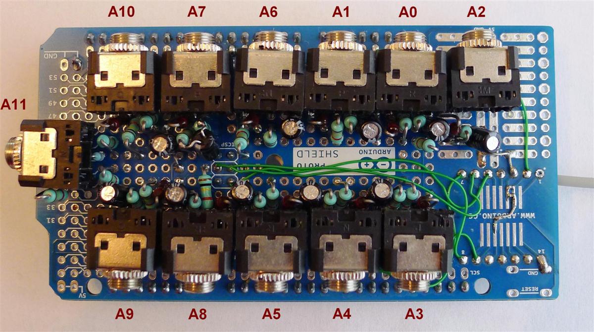 |
EmonTx shield - Bottom  |
|
Fuse box - Before 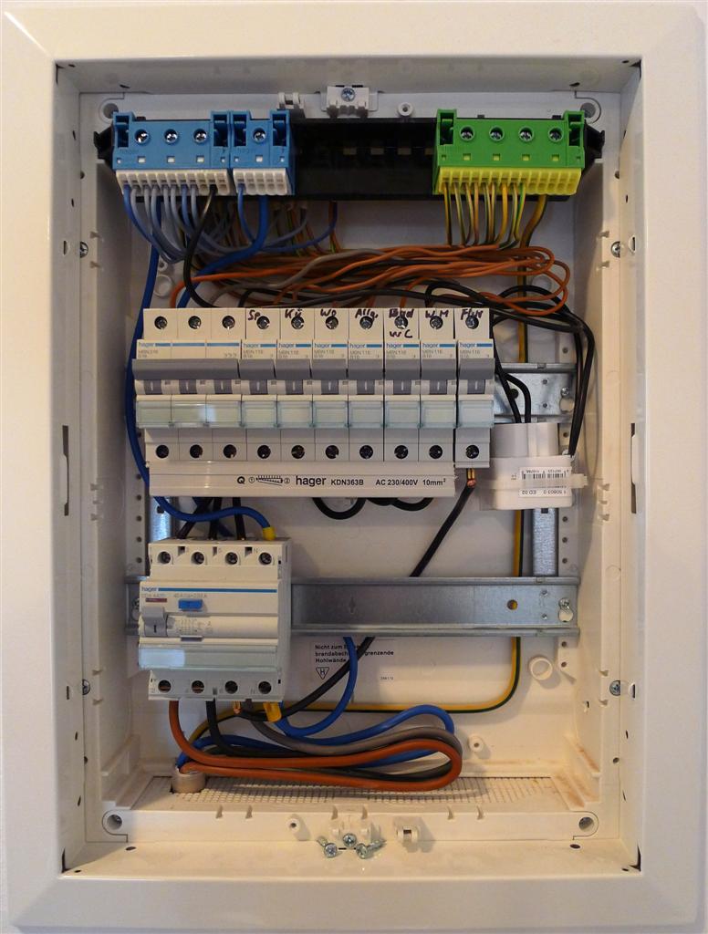 |
Fuse box - After 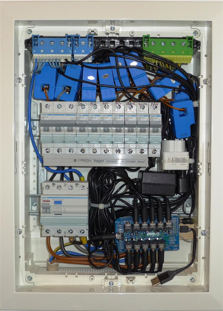 |
3.2. Data Collection Box - Web Server
- NOTE: Raspberry Pi has since been replaced with Ubuntu NAS and Backup Server
3.2.1. Hardware
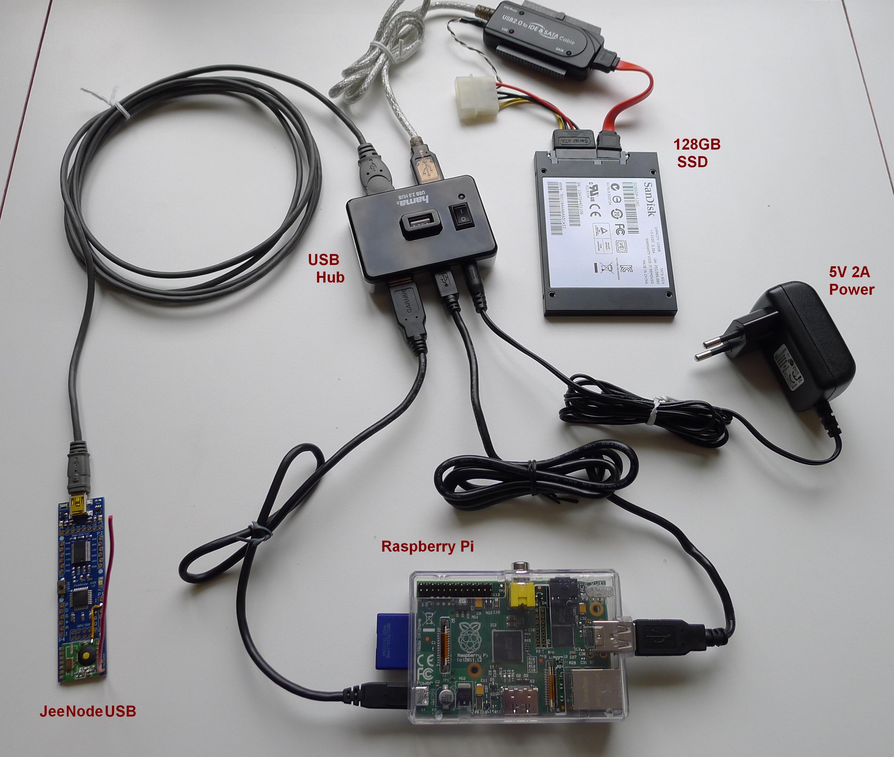
All the components above are powered from a single 5V-2A Adapter through the USB Hub, as explained here: http://www.raspberrypi.org/phpBB3/viewtopic.php?t=9070&p=108006
Plus, I found a hub with a very convenient power switch.
I decided to use a Solid State Drive mainly because it is silent, after I got fed up with constant rattling of my old HDD.
I also added a small mod to JeeNodeUSB to measure RSSI from RFM12B when packets are received.
3.2.2. Software - JeeNodeUSB
- Here's the sketch running inside this Arduino-based JeeNodeUSB: EmonRxRPi.ino.
- The configuration of RF parameters in this sketch is hard-coded. Modifying config at run time through emonhub is not implemented, at this time.
3.2.3. Software - RaspberryPi
- I started with installing EmonCMS pre-built HDD image dated 30.11.2013. It is quite old, but the newer image from 20.01.2014 didn't work. See this thread: http://openenergymonitor.org/emon/node/3688 (update: there seems to be a fix now! should give it a try.)
- Hardened SSH with key files and changed default access port. For that, modified firewall (ufw) rules by adding the new port there.
- Disabled registering new EmonCMS users: http://openenergymonitor.org/emon/node/2116
- Enabled site Password, HTTPS and other security enhancements:
http://blog.al4.co.nz/2011/05/setting-up-a-secure-ubuntu-lamp-server/
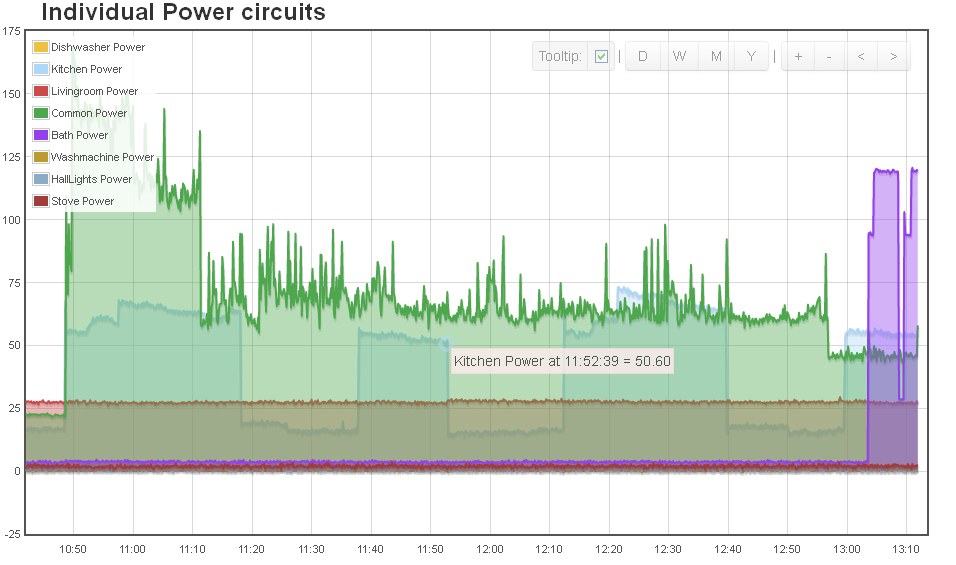
https://help.ubuntu.com/10.04/serverguide/httpd.html - Finally, configured some Feeds and Dashboards in my running EmonCMS:

4. Next Steps
Something to think about...
- Adding Temperature / Humidity sensors. Indoor and Outdoor.
- Tying in some hardware controls, to remotely switch things on/off, for example.
- Creating a plugin for my MediaPortal box to show dashboards in it!