1. The Purpose (Mission)
- Monitor, archive and analyze energy consumption in the house
- Visualize historical consumption data
- Access data remotely from Web
- Eventually include data from other sensors, like temperature, pressure, humidity, motion, light, security, etc.
- UPDATE: Temperature, Pressure and Humidity sensors added: Additional Sensors for Home Energy Monitor
2. Components
- Concept based on OpenEnergyMonitor project
- Hardware based on Arduino and Raspberry Pi platforms
- UPDATE: Raspberry Pi has now been replaced with Ubuntu NAS and Backup Server
- Software: Arduino IDE, EmonLib and RFM12B library by LowPowerLab
3. Progress Report
3.1. Measurement Box
To begin with, I looked at the electrical fuse box in my apartment and noticed that I have 10 or so circuit breakers leading to separate electrical house circuits. I thought that it would be nice to monitor these 10 output lines individually and independently. This way I could have detailed power data as well as compute total house consumption.

When I removed the plastic cover, I noticed that there is quite a lot of space under it, so I hoped I could nicely fit all required hardware inside and hide it from view.
3.1.1. Hardware
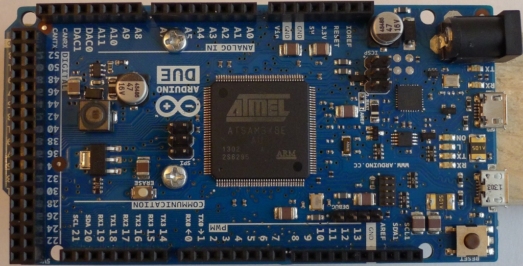
As far as I could see, the original EmonTx approach from OpenEnergyMonitor was to measure current at the input to the breakers. This could be the result of limited measurement speed and/or limited processing power or the Arduino Uno -based hardware. EmonTx has only three current probe inputs with 10-bit resolution. So, instead I decided that I'd need faster processor, more analog inputs and 12-bit ADC resolution. In other words, this Arduino Due board:
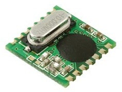
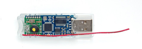
The next logical step was to test wireless communication between this sensor controller and whatever the base might be. For this I purchased a couple of RFM12B modules and a JeeLink from JeeLabs shop:
(NOTE: JeeLink was later replaced with JeeNodeUSB)
|
|
|
3.1.2. RFM12B library for Arduino Due
As a starting point, I used a great port of RFM12B library to C++ by Felix of LowPowerLab.com
Turned out, this library was not compatible with my ARM-based Due board. So I spent the next few weeks on modifying this code and eventually made it to work on my Due. The files are below. Just unzip this into library folder of the Arduino IDE and don't forget to select Due before compiling ;)
https://github.com/icboredman/RFM12B/tree/arduino_due
Not all functionality has been implemented yet, like sleep mode, but overall it does work.
3.1.3. Current / Voltage Sensors
Once I had RF communication working properly between Due and JeeLink, I started working on setting up sensors.
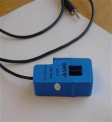
I purchased 12 non-invasive current probes and 1 AC-AC voltage adapter:
 |
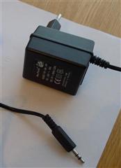 |
Here is a great explanation of Power measurement theory using these sensors.
You can download a complete schematic diagram of my energy monitor here:
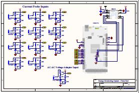
As you can see, I used 22 Ohm burden resistors, which gave me more than enough head room to measure currents up to full range of SCT013 (100A). In addition, to measure line voltage using AC-AC adapter, I adjusted resistive divider to 100K - 6.6K, which slightly reduced resultant voltage range at the Arduino to below 3.3V p-p.
I soldered all components onto this Proto Shield for Arduino MEGA, which also fits perfectly to Due.
UPDATE (Jan. 2016):
Following a suggestion to convert the original crude wire-solder design into something that could be easily duplicated and manufactured, I've taken on Fritzing. I must say, it is a pain-in-the-***. Nevertheless, here's the result, if anybody wants to try it:
http://fritzing.org/projects/emontx-shield-for-arduino-due
Warning, I have not tested this Fritzing design myself, so try at your own risk ;)
In order to utilize full 12-bit ADC resolution of Arduino Due, I reworked original EmonLib library of OpenEnergyProject. Here's my modified source code:
https://github.com/icboredman/EmonLib/tree/feature/12bit_3phase
This mod also contains 3-phase buffer-and-delay algorithm, since my CT inputs are connected to all three line phases, but my AC_AC voltage adapter is connected to only one of them (obviously).
And finally, here's the Arduino sketch that ties this all together:
At the end, after adjusting calibration constants, I was able to see this raw dump of sensor data, occurring every 2 sec:
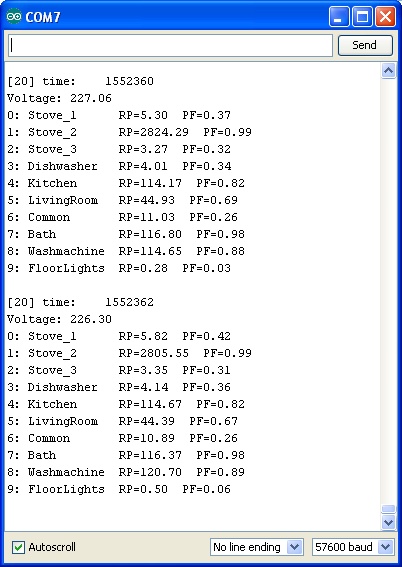
NOTES:
1. The above formatted output was generated using this test sketch EmonRxUno.ino, not to be used in working system.
2. The Arduino sketch for a working RaspberryPi-based system is here: Software
3.1.4. Fitting it all inside my fuse box
Here I will let pictures tell the story...
|
Arduino Due and my EmonTx Shield 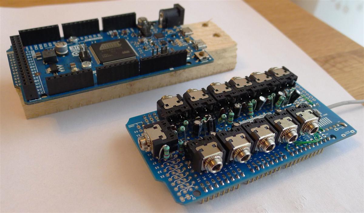 |
|
EmonTx shield - Top 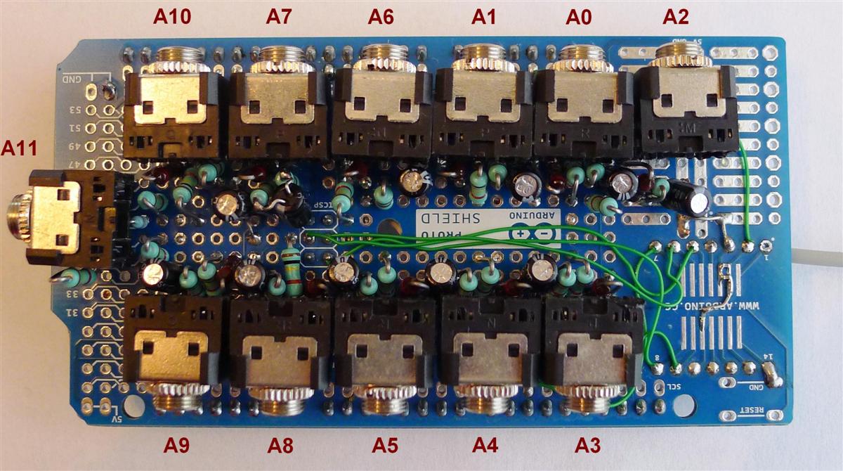 |
EmonTx shield - Bottom  |
|
Fuse box - Before 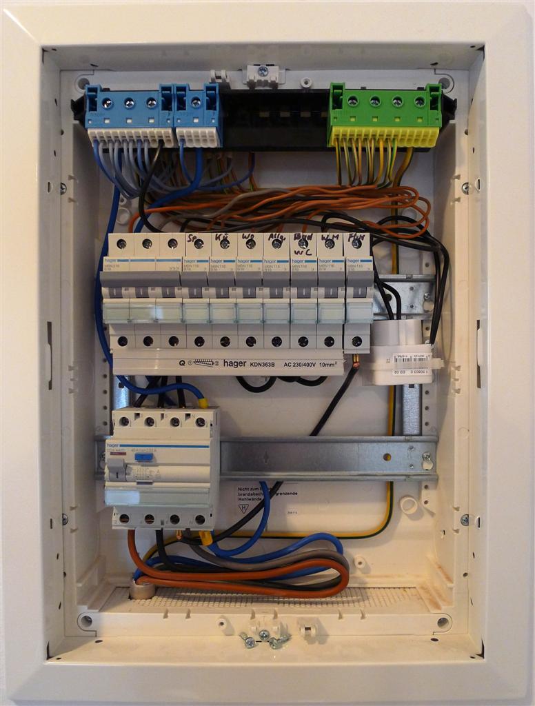 |
Fuse box - After 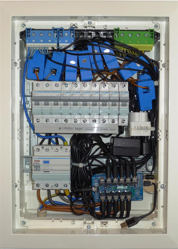 |
3.2. Data Collection Box - Web Server
- NOTE: Raspberry Pi has since been replaced with Ubuntu NAS and Backup Server
3.2.1. Hardware
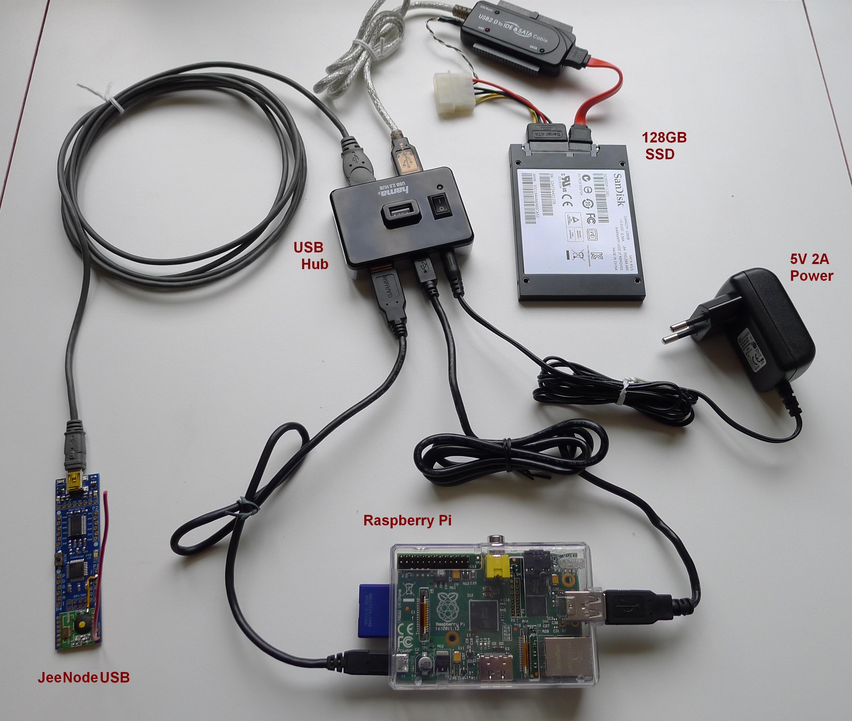
All the components above are powered from a single 5V-2A Adapter through the USB Hub, as explained here: http://www.raspberrypi.org/phpBB3/viewtopic.php?t=9070&p=108006
Plus, I found a hub with a very convenient power switch.
I decided to use a Solid State Drive mainly because it is silent, after I got fed up with constant rattling of my old HDD.
I also added a small mod to JeeNodeUSB to measure RSSI from RFM12B when packets are received.
3.2.2. Software - JeeNodeUSB
- Here's the sketch running inside this Arduino-based JeeNodeUSB: EmonRxRPi.ino.
- The configuration of RF parameters in this sketch is hard-coded. Modifying config at run time through emonhub is not implemented, at this time.
3.2.3. Software - RaspberryPi
- I started with installing EmonCMS pre-built HDD image dated 30.11.2013. It is quite old, but the newer image from 20.01.2014 didn't work. See this thread: http://openenergymonitor.org/emon/node/3688 (update: there seems to be a fix now! should give it a try.)
- Hardened SSH with key files and changed default access port. For that, modified firewall (ufw) rules by adding the new port there.
- Disabled registering new EmonCMS users: http://openenergymonitor.org/emon/node/2116
- Enabled site Password, HTTPS and other security enhancements:
http://blog.al4.co.nz/2011/05/setting-up-a-secure-ubuntu-lamp-server/
https://help.ubuntu.com/10.04/serverguide/httpd.html - Finally, configured some Feeds and Dashboards in my running EmonCMS:

4. Next Steps
Something to think about...
- Adding Temperature / Humidity sensors. Indoor and Outdoor.
- Tying in some hardware controls, to remotely switch things on/off, for example.
- Creating a plugin for my MediaPortal box to show dashboards in it!
Comments
Thanks for any tip.
Radovan
Since as a starting point I used RFM12B library from LowPowerLab, which I modified to work on Due, you would also need to use this library (unmodified version, for Uno) on the receiving end. Here's the link to LowPowerLab's library:
github.com/LowPowerLab/RFM12B
and here's my Uno sketch that uses this library:
boredomprojects.net/images/Articles/HomeEnergy/EmonRxUno.ino
I hope this helps!
Let me know your progress.
If you find a way to talk to 69 on Due, please share! :)
I'm also trying to use the RFM69 with the due but i've stopped for lack of time. Maybe on year's end i'll resume it. We could talk more then. And if you find how to do it , please share .
Since i wanted to monitor some more channels i bought another 4 CT (the nano has only 8 analog inputs, so 1x voltage and 7 times CT)
I used your code (ino from the zip) and changed it to output to serial (no rf) and copied the calib and phasecal for the voltage sensor and the 3 original CT connectors.
However, when calibrating the new ones, i found that phasecal for the new sensor connected to phase 1 was ok (1.00), but the ones connected to phase 2 had to be changed a lot: from 1.28 in the old setup to 16.5 in the new one.
I used old pcb with the voltage and 3old CT's and swapped the nanduino. the 4 new ct's are connecteed to a new pcb via a cat5e wire
Since the first 3 ct's are not easily removed, i cannot recalibrate them to check if the phasecal var is ok.
Do you have any idea why the phasecal changed so much for the new CTs?
I hope this helps. Let me know your progress.
I changed the values PHASE2 and PHASE3 back to the original 8 and 17, however this did not solve it...it got worse: my phase3 (the old ct) got reversed (negative usage)
@radovan: could you tell me how you did that? (and do you have any idea why the original one does not have this problem, or is it because of moving from 3CT to 7CT?
any reason to change this?
I thought it would make more sense to initialize lastVCross on the very first cycle, rather than on the second. Either way, this makes not much difference.
I am getting 434/408/408/407/436/407/407 samples per run. powersamples:364/338/338/338/3 65/339/339. Crosscount is always 16.. these with phase2=8 and phase3=17
With these numbers i am getting a negative value on fase3
Is this consistent enough? if so, what values of phase2 and phase3 should i use (1/3 and 2/3 of 408) locks up the atmega...
However, is there a way of knowing if the settings are right? Radovan: you wrote something about putting values in excell? could you please explain a bit more?
- voltage: filteredV from line 117 (this is befor the phase correction, but after the hight pass filters)
- phase 2 or 3: instP from line 158
Radovan, how many CT sensors were you able to successfully run on ATMega at the same time?
Or you can collect directly raw samples (sample V and sample I) and to calculate phaseshift in Excel. Both is possible.
I tested at maximum 7 sensors (I had no more of them at that moment), but its not crucial. Your code has a good algorithm, its timing is controlled by voltage frequency. So it is independent on CPU speed. At slower platform it collects less samples, at faster more of them. ATMEGA speed is from my point of view more than enough even for 15 CTs+ 1 Voltage sensor. Advantage of Due is 12 bit AD resolution. Total measurement time is not related to platform CPU speed.
Am i correct that this is a good result?
www.hetgrensland.be/.../
Try to change related phaseshift value now, whether or not sync of blue and red waves will be shifting too.
I used the varibalble numberofsamples to put the measurements in my arrays... when i used one of my own, i now get nice sin waves (see picture).
Should i still try to change the phaseshift values, of is it good like this?www.hetgrensland.be/graph fase22.jpg
Here it seems that there is a small error: it does not cross through 0 at the same point. Any ideas how i should adjust phasecal3 of should i just experiment?
www.hetgrensland.be/.../
One hint for your further development - for fine tunning I used little serial OLED display instead of boring Excel procedure. I draw my sinewaves in real time then, with phasecal value changing slowly as a control variable of FOR cycle command. Then you can sit in your chair and watch your little TV
Hi, I am coming from a different programming language (PERL) and cant work out how to buffer (store in array/hash?) the phaseShiftedV an filteredI, for printing out after the main loop.
Would it be possible to provide any code to achieve this?
Cheers,
Reagen
Here's one way to do that:
1. add at line 79:
//declare temporary arrays for storing raw data:
double storedShiftedV[PHASE3];
double storedFilteredI[PHASE3];
2. add at line 159:
//store V and I samples for dumping later:
storedShiftedV[numberOfPowerSa mples%PHASE3] = phaseShiftedV;
storedFilteredI[numberOfPowerS amples%PHASE3] = filteredI;
3. add at line 194:
//dump stored samples:
Serial.print("numberOfPowerSam ples="); Serial.println(numberOfPowerSa mples);
Serial.println("Shifted-V\tFil tered-I");
for(int i=0; i
Here's a link to complete file:
boredomprojects.net/.../...
I've just uploaded to the due and it works fine for a few samples and then starts getting odd results. Here is the output:
numberOfPowerSamples=3982
Count,Shifted-V,Filtered-I
0,1001.37,-0.76
1,1004.54,-0.76
2,995.04,0.24
3,989.07,-0.76
...[truncated for comment]
60,1038.93,0.22
61,1039.16,-0.78
62,1029.52,-0.77
63,1023.41,0.22
64,1025.79,-0.77
65,1012.83,-0.77
66,1013.26,0.23
67,1011.89,-0.77
68,-0.76,0.00
69,-0.76,0.00
70,0.24,ovf
71,-0.76,ovf
72,1.24,0.00
73,1.23,0.00
74,-0.77,ovf
75,-1.76,0.00
76,-0.76,0.00
77,0.24,nan
78,1.24,0.00
79,1.23,0.00
80,0.23,ovf
81,0.23,-0.00
82,-0.77,0.00
83,0.23,-0.00
84,-0.76,0.00
85,-0.76,-0.00
86,-0.76,0.00
87,1.24,ovf
... until the next cycle then repeat
Update: seems like it is always going odd on count 68 (each cycle)
Are you using Due or some other board?
What are your PHASE2 and PHASE3 constants set to? For Due they should be around 65 and 130, which represent nr. of samples for 120° and 240° of a cycle. That's why 2 cycles of data should be around 400 samples.
Also, make sure you set ADC to 12 bits with analogReadResolution() call, as in the example sketch.
I've come back to this & have it all working but still trying to figure out calibration. How do you know which wire (red/white/blue) is which phase? I used this link: i.stack.imgur.com/HUD42.jpg (I'm in Australia) but my PH2 & 3 calibration numbers are quite large in order to achieve sensible numbers, and PH3 reports as negative. A0 is spot on, as is the voltage (which is connected to the same phase as A0/Red), using a 2000W kettle.
emon[0].voltage(11, 348.0, 1.6, 1);//RED
emon[0].current(0, 98.8);
emon[1].voltage(11, 348.0, 2.0, 2);//WHITE
emon[1].current(1, 820.0);
emon[2].voltage(11, 348.0, 3.0, 0);//BLUE
emon[2].current(2, 220.0);
emon.calcVI(16,2000);
EmonTx.voltage = (float)emon[0].Vrms;
Results:
V: 243.24
A0 rP: 1733.49
A1 rP: 1723.25
A2 rP: -1796.23
I used the same CT clamp for each calibration & ensured it was clipped on in the correct orientation.
Start: 613 millis
numberOfSamples=5438
numberOfPowerSamples=4332
crossCount=16
End: 773 millis
Start: 773 millis
numberOfSamples=5328
numberOfPowerSamples=4226
crossCount=16
End: 933 millis
Start: 942 millis
numberOfSamples=5378
numberOfPowerSamples=4270
crossCount=16
End: 1102 millis
I'm using a Due and have set 12 bit resolution. PHASE2 is set to 65 and PHASE3 is 130, but as my sample size is so large, perhaps these numbers are not right?
Do you have any ideas on what I should look into next? Maybe I need a script to test the resolution of my Due?
Any help would be greatly appreciated. Cheers!
Sorry for so many posts! :)
analogReadResolution(ADC_BITS);
analogReadResolution(ADC_BITS); // DUE can have up to 12 bits of ADC resolution
and have confirmed it is detecting the arm architecture and being set to 12, as per:
#if defined(__arm__)
#define ADC_BITS 12
#else
#define ADC_BITS 10
#endif
Thanks
Real Power, as I understand it, is a measure of power doing actual work. Whereas the Apparent Power also includes a component of Reactive Power in it, which produces no actual work. Besides, if I'm not mistaken, the utility company meters and bills us based on Real Power.
Here's a nice explanation about this topic: openenergymonitor.org/.../...
Cheers!
Ahh yes that does make sense :)
Thanks for explaining and the extra info
emoncms.org/.../inputsandfeeds
Are you in a 3 phase 110v location by any chance?
Jos
However, the JeeLink 868 is no more available in JeeLabs shops. Have you any clue for an ersatz ?
Thank you very much in advance,
Arnaud
Right, JeeLink seems to be sold out, but, actually, I used JeeNode USB instead. It is very much the same thing, except without the case. digitalsmarties.net/.../...
Thanks a lot for the project. I'm making.
I want to ask if I can takehttp://shop.seegel-systeme .de/Module/Raspberry-RFM-SMA.h tml this instead of Jeenode ( digitalsmarties.net/.../...)
Thanks a Lot
Walter
I'm sure it is possible. Although you will need to install a custom script to the Pi to get it to work. I have no experience with it, but you may try python script from the bottom of this page:
www.seegel-systeme.de/.../
great...
Walter
Thanks, John!
Can you tell me if the ATmega2560-16AU Board and Mega 2560 R3 Module are compatible with your sketch?
Or can the due be replaced with a cheaper alternative?
Thanks
The sketch is probably compatible, however the RFM12 library is definitely not. You might need to use original library for uno from lowpowerlab. Also, the 3-phase current algorithm may need to be redone to work on uno board. See previous comments by Radovan on this subject.
Hope that you can help with the following...
I'm not able to get the RF link running using the RFM12B library from lowpowerlabs on a Arduino Uno and the RFM12b_Due on the Arduino Due board. I'm using the Jeenode USB on a windows PC together with Python to "Listen". WHen I use the Arduino Uno together with the Jeelib library, I receive data fine on the windows PC. The example test sketches supplied with the Jeelib libraries work. As soon as I switch to the RFM12B libraries from Lowpowerlabs, and use one of the test sketches here, then I receive nothing on the windows PC. The RFM12B sketches compile normally and on the serial output it shows it is transmitting data. What could be wrong?
There could be numerous things that go wrong. I would try to isolate the problem by putting original lowpowerlab library on both JeeLink and Uno. If that works, the receiving end is not the problem. Then, I would replace the transmitter with Due and the modded library, leaving receiver untouched.
Please try it and let me know what you find.
After testing the RFM12B link with the send and receive sketches, which worked fine, I tried the EmonTxDue.
On the receiving side, I recognise the node nr. but the rest seems scrambled. Please see the screenshot.
Could you give me another pointer in the right direction please?
Kind regards, Gerard.
D:\Users\Gerard\Documents\Arduino\libraries\EmonTxDue\screendump.jpg
Serial.print((char)radio.Data);
But per 10 sensors I get much more data, than 10* power plus one time voltage plus timer.
I'm very much a newbie to software... Can you please let me know what sketch you are using on the receiver side or perhaps send me a copy?
Here's my receiving sketch: boredomprojects.net/images/Articles/HomeEnergy/EmonRxUno.ino
If you still have problems send me your sketch and we will take a look.
please, can you post nodes section of your emonhub.conf? I have a problem to define datacodes.
I have used receive section of your EmonRxUno.ino.
My emonhub.log contains these errors:
2015-03-01 21:40:36,239 DEBUG Setting RFM2Pi frequency: 868 (8b)
2015-03-01 21:40:37,243 DEBUG Setting RFM2Pi group: 210 (210g)
2015-03-01 21:40:38,247 DEBUG Setting RFM2Pi baseid: 1 (1i)
2015-03-01 21:40:39,269 DEBUG 1 NEW FRAME : 1425246039.27 [20] time: 10517
2015-03-01 21:40:39,272 WARNING 1 Discarded RX frame 'non-numerical content' : ['[20]', 'time:', '', '', '', '10517']
2015-03-01 21:40:39,478 DEBUG 2 NEW FRAME : 1425246039.48 Voltage: 1.55
2015-03-01 21:40:39,481 WARNING 2 Discarded RX frame 'non-numerical content' : ['Voltage:', '1.55']
...
Thank you for your response in advance.
Sorry, I guess I wasn't clear which sketch is meant for what purpose. The above sketch EmonRxUno.ino was only meant to be used for debugging purposes. In a working system based on emonhub, you will need a different sketch. Here it is: boredomprojects.net/images/Articles/HomeEnergy/EmonRxRPi.ino
I updated the main article now to make this point clear.
I think this should work now. Let me know.
thank you for your response.
I have edited my receiving sketch - have to remove radio.getrssid and radio.getgroup, because they are not in original lowpowerlabs rfp12b lib.
My sketch is here:
pastebin.com/fi8PXGM9
I have set emonhub.conf nodes section this way:
datacode = h
Now I can see 21 inputs in emoncms. First one is Mains voltage I hope, but it is getting me numbers around 23-33. Should I do any conversion? I am getting about 1,63V according to my multimeter on A11 input of my due.
Thank you for your help.
thank you for your support.
Two changes I have made recently were to change the number of sensors to 11 and change AC-AC input PIN(mine is on analog9) in Due setup section. Now it works fine!
Thank you very much.
Peter
I'm glad to hear that!
I hope this helps.
energy_monitoring_only.cpp:9:32: error: 'analogReadResolution' was not declared in this scope"
error... Please help
Spark core has 12 bit adc...i checked
Interesting device! I've never heard of Sparc core before, but now reading about it, it looks very cool. I'm afraid I'm unable to help here. Perhaps people who have experience could answer your question?
I will study the docs, in any case. If I think of anything I will post here.
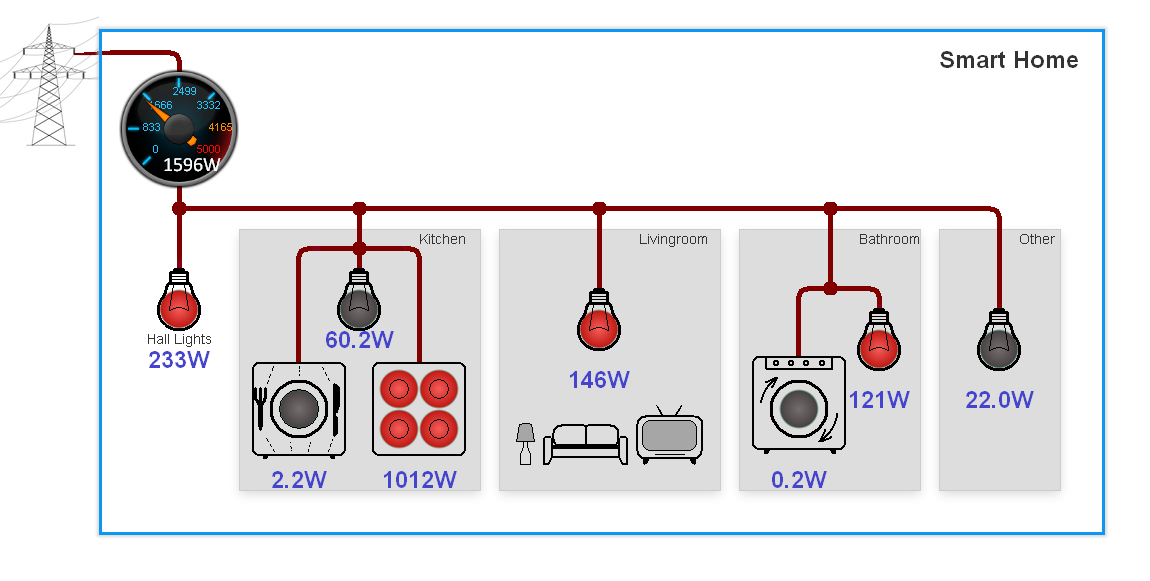
I like you dashboards, you created in EMONCMS. But Im probably blind. How you made that third dashboard, kind of schematics with lines (wires), their nodes and with schematic pictures of house equipment? Did you created it in EMONCMS or with some other tool? Im unable to find those lines, nodes and pictures in EMONCMS menu. Could you share with me your know how, please?
Thanks
Radovan
It was real pain in the ass, actually. It is just a picture: boredomprojects.net/images/Articles/HomeEnergy/plan4_2.png. And the light bulbs are LED elements. The difficult part was to align everything. For this I took a capture of dotted background and drew my lines according to it, using MS Paint. LED colors are controlled from EVENT commands, depending of values of various power feeds.
I hope this helps.
Excellent projet!
J'ai 3 sensors CT différents (YHDC) :
TA17-08
TA12-100
SCT013-030
Que je veux d'abord tester.
Je veux les mettre sur la MEME PHASE! (vérification-étalonnage!)
1-Dans exemple" ArduinoDue_3phase" peut-on utiliser un Arduino Mege 2560?
2-Dans "ArduinoDue_3phase ligne 19:
Message error: analogReadResolution(ADC_BITS) ; no
identify in the scope. (avec Mega 2560!)
Merci beaucoup de me répondre.
Georges
Danke!
2. The function AnalogReadResolution() is only available on Due, not on Mega 2560. arduino.cc/.../...
So, try commenting out this line and the code should default to 10 bits ADC resolution. It is not ideal, but it should work.
1. The RFM12 library is also not compatible with Mega, so you might need to use original library from lowpowerlabs. See some earlier comments by Radovan.
Sorry for English :)
Bei ArduinoDue_3pase.ino:
emon[0].voltage(11, 334.0, 2.0, 2); // Voltage: pin, calib, phasecal, line phase.
Verstehe ich nicht:
11=A11=ok!
334.0= calibration=eichung=ok!
2.0=phasecal=??
2=line phase=phase Nummer in einem 3phasen system??
Vielen Dank für die Antwort!
Georges
> 2.0=phasecal=??
openenergymonitor.org/.../...
> 2=line phase=phase Nummer in einem 3phasen system??
Genau! 1. phase muss der mit Spannungsadapter sein.
Kleine Frage fûr die CT hast Du die SCT-013-000 (100A) ohne Rburden oder SCT-013-030 (30A) mit Rburden?
Vielen Dank!
Aus La Reunion
Georges
Meine Strommesung scheinen mir falsch!
Im hauptprogram steht:
emon[0].current(0, 97.7); Ich habe meine Eichung mit einer Kaffemaschine (1000W) I=4,13A U=222V
durchgeführt.so musste ich die Eichung auf 89 einstellen.
Bishir alles Ok. Aber stelle ich die KMaschine ab, Strom aus, messe ich immer noch I=0,24A !!
Wie kommt das?warum nicht 0?
Habe die "OpenEnergieM.."gelesen aber keine Spurr!
Habe alles gleichgebaut wie vorgeschrieben (Schaltugen, SCT013-000 (Rl=22 Ohms-U=3,3V) ausser Arduino mega 2560.
Bei der "Voltage" Messung ist alles OK! (Eichung=343)
Ich brauche Hilfe,
Vielen Danke im voraus, und noch bravo!
gruss.
Georges
Are you measuring 0.24A with or without Koffee machine connected? If with - the machine may still draw some current in OFF state. What do you measure with CT disconnected? If without - the problem may come from the fact the the library may not be compatible with Mega. To fix this, you may need to adjust constants PHASE2 and PHASE3 in EmonLib_3PH.h file. The values 16 and 34 might be a good start, Look at some earlier discussions in this thread.
Ich habe mir ein ArduinoDUE zugelegt und alte Lampen angeschlossen (Widerstand)=cos phi=1+ arduinoDue und das "ArduinoDue_3phase" probiert.
1 Lampe: I=0.27A cos phi= 0.76 (L=60W).
2xLampen (>60W) I=0.56A cos phi= 0.76
1lampe+1x ecowattlampe I=0.40A cos=0.64 (nimmt ab ist ok!)
So bleibt also cos phi auf dem högsten Punkt= 0.77
Schalte ich die Lampen aus I=0A so stellt sich der cos auf 0 ein=stimmt auch
Fragen: Meine Haus liegt auf einem Monophasensystem, spielt dass eine Rolle 3phasen?
Also warum nicht cos phi=1?
Soweit so gut es ist alles gut.
Ich habe wieder alles von vorn angefangen, so habe ich gemerkt das ich der Fehler war.
Also es funktioniert!
Ich möchte mich entschuldigen...
Und noch Vielen Dank fûr dein Projekt!
Gruß
Georges
Viel Spaß! :)
i have the same setup as you, a fusebox with 10 pieces of 230V circuits...
i have very little space in my fusebox, so i want to use the Honeywell CSLT6B100 5mm current sensors (solid).
sensing.honeywell.com/.../
Is this possible?
What needs to be adapted to the electric Arduino board (resistors etc) for normal functionality...?
Greetings...
I think it might be possible. The only two things I can think of is: 1) since it is not a clip on, you will need to disconnect your line, thread it through this sensor and reconnect it. Not that easy. 2) you need a separate 5V supply for it, if you are using a 3V Arduino.
The circuit may look like that:
can your current Fritzing board be used with above CSLT components as we discussed earlier?
Arduino Due also has 5V supply on one of its pins.
disconnecting and connecting the 230V lines isn't a problem, i'm a 230/400V electric engineer but designing electronics isn't my speciality
just found the Brultech CT's, these are "ready to use", so no need to build them myself. can i use the same capacitor 10uF & resistances 100k/100k ratio for these Brutech CT's as for the Honeywell CT's?
brultech.com/.../...
are you referring to Honeywell or Brultech ;)
The Brultech are Current Transformer type, so you need to use standard connection circuit (cap to gnd) with burden resistor of about 42ohm.
I would not recommend Brultech. Detailed description is missing.
elster.nl/.../...
do you see possibilities to to connect it to the arduino due and get it working measuring and registration together?
Good luck!
How did you do the calibration? Had to do in the fuse box with everything installed? and so how do you know the values are correct?
Or did you calibrated outside with some power meter ?
Thanks
I calibrated each input separately, before intalling the system into the fuse box. I used a 1000W electric kettle (purely resistive load) and a multimeter (voltmeter + ampermeter). You can find detailed description of the procedure here:
openenergymonitor.org/.../...
But when i put them connected on a TV and a cable box, the values were all wrong.
Also, what do you mean TV and cable box values are wrong? As you know, such loads are very reactive (factor < 1.0).
The numbers look good.
I've realised we can't have a high degree of accuracy, and the diference is in some watts. When you spend several Kws per day, it won't matter much,
When I load phase 1 with a resistive load, the power factor goes perfectly to 1. If I put the same load on phase 2, and I adjust the Phase 2 sample delay to maximise the power factor, I only get to a maximum of 0,97.
If I put the same load on phase 3, and I adjust the Phase 3 sample delay to maximise the power factor, I only get to a maximum of 0,95. How can I get the power factor to 1 for pure resistive loads on phase 2 and phase 3?
I do find the phase 2 and phase 3 delay quite different from the original 65 and 130. I have 213, 426. I am using the Arduino due and 11 sensors.
Considering normal measurement error, I wouldn't worry about these differences. To me, 0,95 0,97 and 1,00 look very much the same. I'd say these results are pretty good.
As far as your delay constants, could it be that you have them 2x or even 3x what is necessary? In this case, the system will still function normally. Other than that, I can't think of any other reason why they would be so much more than mine.
Good luck!
Great project! I am trying to recreate this and am having issues with RFM12B communication. I have confirmed the Jeelink can see random 433MHz data using the preinstalled RF12demo. I then installed the RFM12B Receive.ino sketch from lowpowerlabs. I have installed EmonTxDue.ino onto my Due and when it tries to transmit, the LED turns on and doesnt turn off. I have added some debug code (ouput below) and it gets to the RFM12B:SendWait subroutine and rxstate stays on 6, never changing. Are you able to offer any ideas on where I should be looking next to solve this?
Thanks in advance,
Reagen
Initializing...
RFM12B::Initialize
rxstate 0
RFM12B::InteruptHandler
rxstate 4
Transmitting...
RFM12B::Send
rxstate 4
RFM12B:CanSend
rxstate 4
RFM12B::ReceiveComplete
rxstate 4
RFM12B::ReceiveStart
rxstate 4
rxstate 5
RFM12B::CanSend
rxstate 5
rxstate 7
RFM12B::SendStart
rxstate 7
RFM12B::SendStart
rxstate 7
RFM12B::SendWait
rxstate 6
Hi
Have you solved this problem? My board resets after about 8 seconds because of the rfm12b. If i comment the send rf comand the led blinks normally
Thanks
Yes I did solve my issue. It was a bad RFM chip. I switched it out with another and everything started working normally.
Cheers.
Sounds like the problem might be with SPI somehow. The state machine is trying to send, but gets stuck after the first preamble byte. Which version of Arduino software are you running? I know this is obvious, but have you selected Due as the target?
Can't think of anything else at the moment. :(
I'm running version 1.6.6 on linux and have selected the Due "Programming port" as the board.
Is there a way to throw a multimeter onto the FM12B radio to see if all the pins are connected correctly? I've confirmed 3.3VDC to the VCC and GND pins, but dont know how to confirm the others are definitely correct.
Cheers,
Reagen
You may try to look at MOSI, MISO and SCK pins with a scope. If you don't have one, a multimeter might show a normally 0 volts with small changes when SPI transfer is going through. Pin D10 (SS) should show normally high with small deviations towards zero during transfer.
Good luck!
When compiling EmonRxRPi.ino gives me an error: "error: 'class RFM12B' has no member named 'GetRssi'"
Can you tell me where I'm wrong?
You are not wrong. The RFM12B library does not have function GetRssi. You'll need to put one in, as explained here: forum.jeelabs.net/comment/6203.html#comment-6203. If you run into difficulties, let me know and I'll post complete code here.
Good luck!
I'm not very familiar, so I ask if you could explain to me in detail and code / libraries that should be added?
here's the modified RFM12B library that includes RSSI reporting: boredomprojects.net/images/Articles/HomeEnergy/RFM12B_rssi.zip
Happy New Year!
i really wont to make this but im not enginier so its hard to follow how you connect all these current probes so do you maybee have some design of emon in software like fritzing or any it will be very hellpful. or you make me some directions howe to soldier all these elements. i will be very greatfull!!
To be honest, I've heard the name Fritzing, but didn't know much about it before. Thanks for pointing me to it. I think this is a good idea. I will look into creating a board design using Fritzing and will post it back here soon.
yes would indeed be a great support if you can supply us a Fritzing PCB, thx!
I have never tried it myself, though, so can't give any specific advice. Good luck!
The actively maintained library for the ENC28J60 is "EtherCard" and it does not support the Due according to their page. I have read however that the w5500 works with the due using the arduino Ethernet library.
www.arduino.cc/.../ethernet
I was wondering if the RFM12B board has given you any problems. My emontx board is reseting after 8 seconds or so. But if i disable the comand rf12_sendWait in the code it doesn't reset
What code are we talking about? File name and line number would be helpful.
But, no, I don't remember RFM12 giving me these problems.
Ok, I did it! sort of...
fritzing.org/projects/emontx-shield-for-arduino-due
There are still 6 lines which I could not route, so they need to be completed using wires.
I'd appreciate any comments and reports on whether this design works as expected.
I have no existing hardware, but am looking to monitor at a main panel, and a branched subpanel, for per-circuit measurements. Probably a 3-4 month project before I have this live. Also not sure which CT connectors would be ideal for accuracy, without breaking the bank.
I'm glad to hear that! Really looking forward to your review of the board.
I found a bunch of these connectors on Amazon, for example, 20pcs for 4eur, or so. Just search for: "5 pin 3.5mm socket pcb".
Good luck!
File: etmontx_lib
Line 9
I think my RFM12B is toasted. Do you know if the RFM69 is compatible with the due?
That's why i was asking, If you had to change the rfm12B to be compatible, this one probably has too.
When you say 'original' do you mean there's another?
Thanks
Ex.: emon[0].voltage(..., ..., ..., 1);
Thankyou for sharing this project. It has inspired me to learn more about electronics.
I am partway through building a similar system , and have recently completed calibration for the AC-AC transformer and my first CT clamp.
The calculated Real Power matches the power measured by a commercial power meter, and the power factor is 1.00 when under load with the default PhaseCal of 1.7 (I took a guess that my wall outlet was on phase 1).
My voltage calibration constant (1458) and Current calibration constant (420) are a lot higher than those in your sketch (and on the openenergymonitor website) though.
Do the high calibration values indicate that I've made a mistake somewhere?
Thanks.
In case anyone makes the same mistake - In the setup() function of the sketch, I had accidentally commented out the line:
analogReadResolution(ADC_BITS);
With that line uncommented, I could set the calibration constants to more reasonable values, and I'm not seeing any more intermittent NaN values.
Not sure if it means anything but (like Gerard above) I'm also using the Arduino Due, and also had to change the phase 2 and phase 3 delay in EmonLib_3PH.h from the original 65 and 130.
PHASE2=16 and PHASE3=34 resulted in power factor values:
Phase 1 = 1.00
Phase 2 = 0.97
Phase 3 = 0.95
..with the default phase angle calibration values (1.7, 2.0, and 3.0).
It could use some more tweaking, but at least I feel back on the right track.
Thanks again to Boredman for sharing your experience with the world. This is a great project to learn on!
The line analogReadResolution(ADC_BITS) sets 12-bit resolution, instead of the default 10-bit. To be honest, I can not see why this would cause high calibration constants, but, as long as it works now, it's all good! :)
Thanks a lot for kind words!
I do not know if I dabble or anything else there, but graphics with atmospheric pressure is negative. If it can "fix" somehow?
COMMENT MOVED TO: boredomprojects.net/index.php/projects/sensors-for-hems
just wondering: what do you think of the ADS1115 (e.g. de.aliexpress.com/.../...) offering 4 independent A/Ds with 15bit precision for less than 3USD for the arduino.
Any feedback is highly appreciated.
Sensibelchen
This device looks indeed very interesting. Can work from 3.3V or from 5V supplies, high resolution, 4 inputs, should be fast enough for energy monitoring. From reading the docs, it looks like one can attach up to 4 of these devices to a single I2C bus, which would create 16 additional analog inputs! Not bad.
I guess you are thinking about increasing number of CT connections? This might be a good way!
If you do get to use it in your system, please let us all know about your experiences.
Data sheet tells me to get up to 860 samples/sec but all I receive is:
500samples/sec using 1 channel
250samples/sec using 2 channels
170samples/sec using 3 channels
125samples/sec using 4 channels
with one ADS1115 connected to my nano just reading input without any calculations and serial.print. Using the ordinary A0 on my nano I receive up to 9000samples/sec!
I guess I have to wait for my Due to touchdown from china.
I'm powering the Arduino Due via the micro USB programming port, which wasn't an issue until the proto shield was mounted.
Without the proto shield, the Due starts running the Sketch immediately when the USB cable is connected.
With the proto shield attached, the Due powers up OK but I see no LED or Serial activity - like it's waiting for something before executing the sketch. Leaving it for a while makes no difference.
If I press the reset switch on the Proto shield, the Due resets and immediately starts executing the Sketch, green LED's flashing and outputting values to Serial as expected.
Have I done something wrong? Or is there a way of changing this behaviour so the manual reset is not required? I'd prefer if it didn't need manual intervention every time it loses power.
Thanks,
Adrian
I can't remember having this problem, but after some research, these guys seem to have it figured out:
forum.arduino.cc/.../
Bin erst jetzt dazu gekommen!
Auf dem Proto sieht man A0 bis A11
also A0 bis A9 = Strom und A11 Spannung aber kann man nicht auch A10 einsetzen?
Und mit emon[9] hört es auf.
Kann man auf Platz11 define NSENSORS 10 auf 11 stellen?
Danke.
I propose we converse here in English, so that everybody could follow?
There are 11 CT inputs and 1 voltage input. 12 in total.
Inputs #0 to #10 are all the same and all can be used for current measurements. Input #11 is special, to be used only for voltage measurement. In my system I only have 10 CT inputs (not 11), that's why I used data structures only up to emon[9].
I hope this helps.
My ADC tolerates upto 1.5V input and the listed reference voltage is 1.467V. It has a 12-bit ADC and then the counts would be 4096. Since my ADC tolerates upto 1.5V this means every count corresponds to 1.5/4096? Which is 366.21 uV. Is this right?
On line 85: What range is this? Also how is the 0.55 and 0.45 derived?
On line 109-112: If I'm using a 12 bit ADC wouldn't the offset extraction divisor change from 1024 to 2048? My offset is 0.7V.
I'm curious about your design of the voltage dividers. Do you think you could post your schematic diagram? If you didn't use CTs, how did you manage galvanic isolation between AC lines and your circuit?
To answer your question, yes, 366uV per count is correct.
I didn't understand which zip file you're referring to. Please look at github.com/.../12bit_3phase and let me know line numbers from files over there.
There is no galvanic isolation as such. The opamps act as an instrumentation amplifier whose outputs are finally single-ended and fed to the MCU. I'm guessing these serve as some form of isolation between the MCU and the AC mains.
Coming back to the code, I needed only the single phase measurement mechanisms which you've listed here in the EmonTxDue.zip file in the description (under "Update Jan 2016" section).
Here is where I'm stumped:
Line 114 and 118 (from the github 3phase code lib): How does this work? Why is there a 0.996 multiplier?
As for your question, 0.996 is just a ratio, taken from original EmonLib, part of the high pass filter implementation, in order to remove DC component. Here's some explanation: openenergymonitor.org/.../...
Can i swap the 9v AC/AC adapter with
9v pcb mounted transformer (store.comet.bg/.../) ? In this case, do i have to do add more components ?
A few things to watch for:
* EmonLib_3PH.h defines ADC_COUNTS constant. Make sure it is set correctly to 4096 (for 12-bit).
* PHASE2 and PHASE3 constants are highly dependent of CPU speed, so you may need to modify them dramatically.
* Since your ADC range is only 1.467V, you have to adjust resistors in conditioning circuits for all current and voltage inputs, to center the signals in the ADC range as well as to ensure no signal clipping.
I started again with the project and tried to use the due. I got the led to blink and tried your sketch with a breadboard and without the radio board.
I've disabled the radio calls in the code, but the led should blink. When it didn't i've put some Serial.println to debug but they don't appear in the seria monitor.
Out of the blue do you have any idea why? Maybe some settings on the board? I use the programming port.
Thanks
I've tried to do some quick connections and get a reading but the realPower variable gives Nan in the serial output. I copied the calibration and other values from the emontx board i had, and i didn't connect the AC-AC adapter yet.
Is the Adapter necessary ? or it should be giving a value and i'm doing something else wrong?
Thanks
Yes, AC-AC adapter is necessary to calculate realPower and other things. Remember, power = current * voltage !
Check out these guides: openenergymonitor.org/.../...
What kind of power for the board? A USB 5v charger is good? or i need a transformer?
thanks
arduino.cc/.../...
I would like to ask if it is possible to make this project with a bluetooth module which sends all the readings to Android phone instead of making the Data Collection Box above? On tight budget here...
Thank you (Please excuse my poor English)
Yes, it should definitely be possible. There are many BT modules available. You should be able to replace RFM12B code with one for your BT module. However, I have never done this myself and can not help with specifics, nor with how to handle the data on Android.
If you do get it to work, please share!
I was wondering how many ct sensors you can connect to a mega? It has 16 analog inputs but there are mux shields available. This way you can connect 48 analog inputs, but would the mega be able to process them?
boredomprojects.net/.../...
Hard for me to say. You will have a reduction in timing resolution, though, and as a result in measurement accuracy.
My power factor and real power values are all wrong. the current, volt and apparent power are good.
Here some of the code
emon[0].voltage(1, 321.0, 0, 1);
emon[0].current(0, 216.0);
emon.calcVI(16,2000);
and the output
Current pin 0->0.74
Volt pin 0->227.47
realPower pin 0->-0.22
apparentPower pin 0->169.33
powerFactor pin 0->-0.00
Volt pin 1->229.24
Can you give some help?
Thanks
I hope you can make some sense of it
Thanks
startV=2003
startV=2039
SUPPLYVOLTAGE=3300
serialprint : 0.00 40.73 147.57 0.30 0.00
I would take a look at the third parameter to voltage() function - PHASECAL. It should not be zero. This parameter compensates phase error between sampling voltage and current for each phase. It is important to properly calibrate this parameter: openenergymonitor.org/.../...
I want the energy monitor to tell me how much each line is spending in watts. The real value the electricity companies charge is the power=voltagexcurrent, right? If so, then i can forget the power factor.
Is this correct?
I remember somewhere that the ac-ac adapter was connected to the washing machine line. But it has to be alone, right? I mean you can't have the ac-ac and the washing machine line in the same input, do you?
thanks
I suggest you to read on explanation of the theory here: openenergymonitor.org/.../...
I am interested to try out the Home Energy Monitoring system. Could you please let me know how I can order one.
Thanks,
Sharath
As I am looking to do a similar hobby project, I wondered if it would be possible to only use a raspberry pi, equipped with a analog hat, so why did you decide to use a raspberry + an arduino.
Is this because you know the arduino and the libraries to read out the adc, or is it because of some raspberry performance issue making it impossible to only use a raspberry ?
You're right. There's no reason not to use RPi instead of Arduino to do the measurements. There are plenty analog input add-on boards exist for Raspberry to do the job. We just have a to a distinction between measurement box and the data collection box. You need both. And both can be Raspberrys, I suppose.
I used Arduino Due board because it was good enough to do the job on its own, as a single piece, since it has built in analog inputs, so no extra add-ons needed.
I apologize in advance for the stupid question, but:
If we plug in an electric kettle with 2 kilowatts and the voltage is 230 volts, how much should the value of Real Power and Power Factor (what gives the EmonTxDue) as a single-phase power supply?
An electric kettle is a purely resistive load, so, by definition, it's power factor would be 1. Therefore, the real power is calculated simply as voltage * current, in this case = 2 kW.
Here's a good guide: learn.openenergymonitor.org/.. ./...
Cheers!
For EmonTxDue, the exits are:
1 - voltage,
2 - real power of A0
3 - power factor of A0
4 - real power of A1
5 - power factor of A1
....
22 - rssi
the power consumption for A0 = the real power on A0 * power factor on A0?
Is that correct ?
Thanks, Cheers to you too!
Real power = apparent power x power factor.
Apparent power = V(rms) x I(rms)
Power consumption = real power. This is what utility company is charging us for.
So, you can directly take the real power produced by the software as the measure for power consumption. Power factor is just an indication of how reactive (or resistive) your loads are.
Good luck.
I would guess you have not performed calibration yet. Here's a nice guide how to do that: learn.openenergymonitor.org/.. ./...
In general, we cannot be sure that the kettle is indeed exactly 2000W, that's why we need an external multimeter. Also, electronics inside eMon have uncertainties and need to be calibrated against what multimeter shows.
I'm trying to implement this project but i'm bumping into a problem.
I understand the concepts of Real Power and the Potency Factor but i don't understand how they can be measured. How is the coil's Voltage output related with these parameters? And what's the best way to calibrate my coils? I'm using the yhdc sct 013 100mA:50mA coils as well.
Thanks!
Openenergymonitor.org site has many useful guides on these topic. Here's one of them on Voltage adapters: learn.openenergymonitor.org/.. ./...
And on calibration: learn.openenergymonitor.org/.. ./...
Depending on the country, the frequency of AC voltage is 50 or 60 Hz, the analog inputs measure this at a higher frequency, perhaps 200 times per seconds or more, so the system is able to calculate mean or effective voltage and current from these measurement samples.
Power = voltage x current x power factor.
The power factor is the cosinus of the phase shift angle between voltage and current.
So when comparing the voltage and current measurements, the software is also able to calculate the phase angle between voltage and current, which gives us the power factor.
Maybe I should specify my problem. I'm trying to use a multiplixer to increase the number of analg inputs of my microcontroller. With the multiplexer, all coils are connected to one analog input so i can't calibrate each one of the inputs separately.
So my idea was to understand how the libraries work so I could implement all the calibrations, via code, on the output of the multiplexer.
Does that makes any sense? Thanks again.
You would have to rework the library accordingly to insert commands to the multiplexer in the right moments. For example, before each call to calcVI() function.
I used it on the Uno Arduino and it worked everything!
Now I am trying on ESP32 and I can not get a satisfactory result, I made the modifications in Lib for 12 bits and still I have failed.
Have any tips to run this project on ESP32?
Thank you.
Unfortunately, I'm not at all familiar with ESP32, so cannot really give any suggestions. But you would at least need to look at the following things:
* incompatible Analog-to-Digital converter code
* Radio interface might need to be different (not RFM12B)
* PHASE2 and PHASE3 constants are highly dependent of CPU speed, so you may need to modify them dramatically.
In general, it might be a lot of work to adapt to ESP32.
I'm going to try something different, in case I come and inform you and share the solution.
Thank you :)
Also, is there any other way to open the FZZ file, because it just won't install on my system.
BOM
1 Ceramic Capacitor package 100 mil [THT, multilayer]; voltage 6.3V; capacitance 100nF
12 Electrolytic Capacitor package 100 mil [THT, electrolytic]; voltage 6.3V; capacitance 10µF
1 10kΩ Resistor package THT; pin spacing 400 mil; bands 4; tolerance ±5%; resistance 10kΩ
1 6.8kΩ Resistor package THT; pin spacing 400 mil; bands 4; tolerance ±5%; resistance 6.8kΩ
25 100kΩ Resistor package THT; pin spacing 400 mil; bands 4; tolerance ±5%; resistance 100kΩ
11 22Ω Resistor package THT; pin spacing 400 mil; bands 4; tolerance ±5%; resistance 22Ω
1 RFM12b HopeRF Transceiver
1 Generic double row female header - 6 pins package THT; pin spacing 0.1in (2.54mm); hole size 1.0mm,0.508mm; form ♀ (female); row double; pins 6
12 Audio Jack (TRS) 3.5mm package 4Ucon 08780 [THT]; size 3.5 mm; channels Stereo (TRS)
6.3V caps are fine.
that just leaves the capacitors and resistors, are there any brands in particular I should look for? how much strain are these put under? I know from my limited electronics experience that some capacitors can be really awful.
this one seems to be really hard to find in particular:
1 Ceramic Capacitor package 100 mil [THT, multilayer]; voltage 6.3V; capacitance 100nF
EDIT: Fritzing did not load correctly on linux, so i checked it out in my Windows VM, the 100nf ceramic capacitor is for the Wireless Radio, and since I am going to be using ENC28J60 isntead, I can skip that one! yay!
Also for the 22ohm resistor, higher up I seen you called it a burden resistor? is that somehow different from a regular resistor?
EDIT: dont use ENC28J60 the ethercard library does not support it, if your planning to use ethernet use w5500 instead.
The only "strain" the parts are under is the max dissipating power for resistors and max DC voltage for capacitors. The types listed in BOM are more than capable of withstanding the strain in this application.
The 22ohm resistor is called burden because of how it is used in the circuit, not because of its type. Its purpose in the circuit is to conduct and "burden itself" with current generated by the current probe.
I have the rest of the parts ordered and cant wait to put it all together.
It is really great that you shared this because more people really should be aware of the power they are consuming! I really appreciate it! It is hard to believe I have not invested in setting something like this up sooner than now!
I live in the United States, my electric panels only have 110 (single wire to breaker) or 220 (two wires to double throw breaker). I am not certain what this means for the different phases in the code, I do not have any 440. Is there anything that is going to need to be changed with the code because of this?
I am atleast a month away from being able to work on this because of ebay shipping speed.
Since it seems you only have single phase power in your home, I'd suggest to use the original EmonLib software from here:
github.com/.../EmonLib
Best of luck!
I've made simple adaptations to the project but the measurements are not correct. I get the right values of current and voltage but I can't get the right PF values (apparent current seems right but real power is not).
I'm using 2 Analog Pins, one for voltage measurements and one for current measurements. Since these values are right (compared with a certificated and expensive Network analyzer), I assume that my circuits are also rightly implemented. Instead of DUE, I'm using an Arduino Mega 2560 and the circuit for the CT is powered from the 5V power line. For measuring voltage, I'm using a voltage sensor.
Can the Arduino Mega be the problem to the error of PF?
Thanks guys. Best regards!
By changing the value of Phasecal I manage to get the right PF and the right Real Power values.
I'm working with a Phasecal = -1.9. Only a negative value allowed me to get the right PF and RP values. Does that represent a problem?
Thanks again ;)
So for instance my Clothes Dryer and Water heaters both use 220V they are wired to a double pole double throw breaker with 2 hot wires.
I should be able to place the CT clamp around both the wires going to this breaker and be able to measure that 220V circuit with a single CT clamp, correct?
So long as the CT clamp is properly rated, I have read you want to choose a CT clamp that is rated for about 100% of your expected current measured. (I have oredered an inexpensive Clamp meter so I can verify amps under load.)
Check this out:
en.m.wikipedia.org/.../...
but if I clamp around 2 wires that go to the different 110 poles, as with my water heater and dryer then the two cancel each other out.
Thanks!
I also cannot tell what guage it is, thank you.
EDIT: did some reading about breadboard wiring, etc. Seems solid core ethernet wire is a good choice for this type of work.
Thanks! and Great work on this!
If you open the design file in Fritzing, in PCB view you should see the six dotted lines representing connections that must be completed by soldering wires. Probably it is easier to wire those on the bottom side of the board.
Let me know how this works out.
After a bit of reading im not sure the esp32 is a good idea, seems its less reliable readings than some ADCs
edit: I am thinking for the panels were i need more than 11 CTs I could possible add a MCP3208 to the arduino. I will have to read up on this some more.
BAH! I will also note that I should have looked more closely at the audio jack style. You want to use audio jack that elevates the audio jack plug away from the PCB, if the audio jack you use has the hole for the plug practically flush with the PCB, then it does not really work that well. The ones used by boredman look similar the replacements I just ordered.
I am now waiting on a ZMPT101B for the voltage sensor instead of using the AC-AC adapter. I understand this is not as safe, I am willing to accept that and will be sure that the module and wires going to it are secured and insulated well. I will also make sure there is a fire alarm right by the panel.
I also ordered a cheap DSO150 Oscilloscope to help with calibrating the ZMPT101B
i.imgur.com/cIPcmNn.jpg
i.imgur.com/UddK2yK.jpg
i.imgur.com/WJBYR7W.jpg
i.imgur.com/HdGP9su.jpg
i.imgur.com/xZrw58M.jpg
i.imgur.com/NLrCYgX.jpg
i.imgur.com/epTiXaY.jpg
It appears the 3.3v to the RFM12B module is not routed through on the board. I've solved it by running another wire from the 3.3v to the positive of the capacitor for the RFM module.
Cheers
Reagen
Thanks for pointing this out!
RSS feed for comments to this post