UPDATE (Jan. 2019): Next iteration of this project is here: Robot Navigation using Stereo Vision - Part 2
1. Purpose
- Experiment with robotic vision and autonomous navigation
- Improve Mobile Robotic Platform to be better suited for navigation
- Learn and play with ROS (Robot Operating System)
2. Components
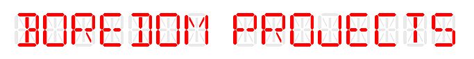
- Minoru 3D web camera
- Raspberry Pi 3
- Teensy 3.2 microcontroller
- DFRobot Cherokey 4WD Mobile Platform
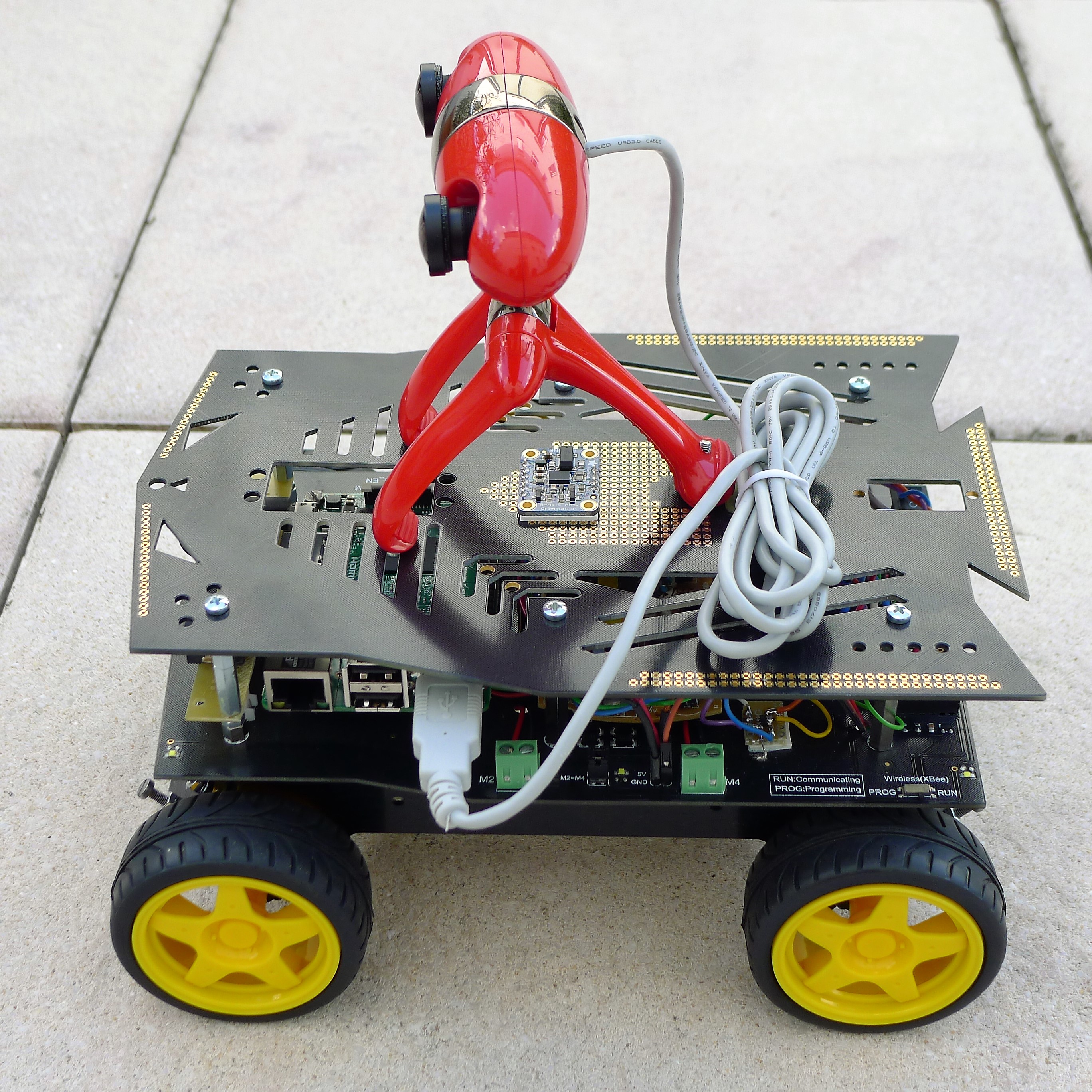
- NiMH 2500mAh AA batteries (6 pcs)
- Graupner 6425 NiMH charger
- 5V Step-up/down Voltage Regulator S18V20F5
3. Results
Top half of the video shows real live robot avoiding an obstacle and the bottom half is the robot's perception of the world, as shown in RViz tool. Dark spots represent occupied space, white lines are simulated laser scans and big red arrow sets the goal position and orientation.
4. Progress Report
4.1. Intro
It seems that the majority of current indoor navigating robots use various 2D sensors to find their way in the environment, such as laser scanners, ultrasonic range finders, mechanical or infrared proximity sensors. Stereo vision sensors, however, are somewhat more difficult to use because they provide a huge amount of highly varying information. However, after right processing, a detailed 3D representation of the world can be extracted. Cameras are also much cheaper than laser scanners. Maybe that's why there are no animals that grow laser rangefinders on their heads.
The purpose of this project was to continue my study of computer vision algorithms, such as, but not limited to, those provided by OpenCV library. In addition, I am fascinated with general robotic navigation topics and wanted to "get my hands dirty".
This project builds upon the Mobile Robotic Platform, which I created specifically for the purpose of experimentation with autonomous navigation. This platform was modified somewhat to fix various hardware issues. It has also been equipped with Minoru stereo camera as a primary sensor.
4.2. Hardware
4.2.1. Robotic Platform
Since the first iteration of the platform, several new sensors/features have been added, such as:
- BNO055 IMU sensor
- Wheel optical encoders
- PID motor control
- Battery charge estimation using Coulomb counting
- Packet-based serial communication with master processor (RPi)
To cope with this extra processing requirements, slave controller Arduino Pro Mini has been replaced with more powerful Teensy 3.2, which is a 32-bit Cortex M4 running at 96 MHz.
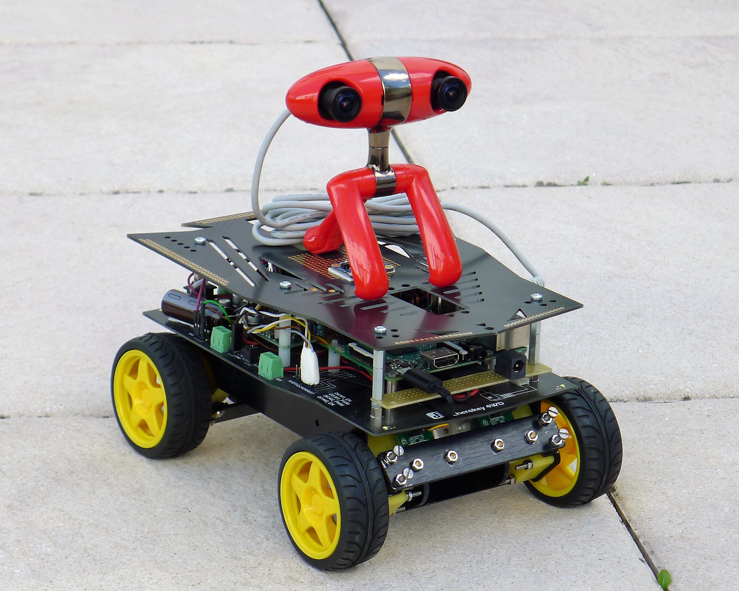
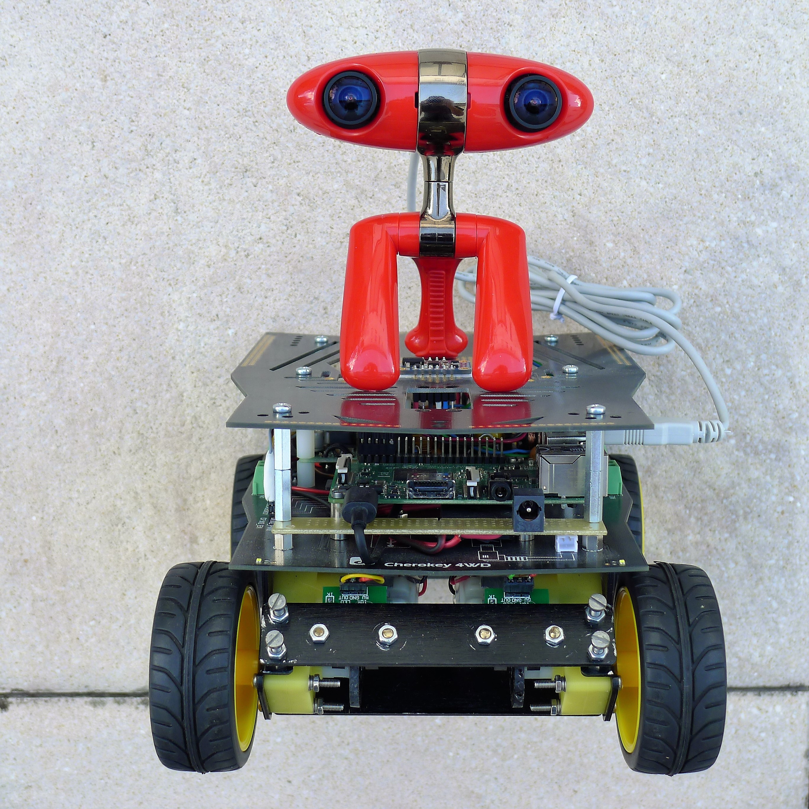
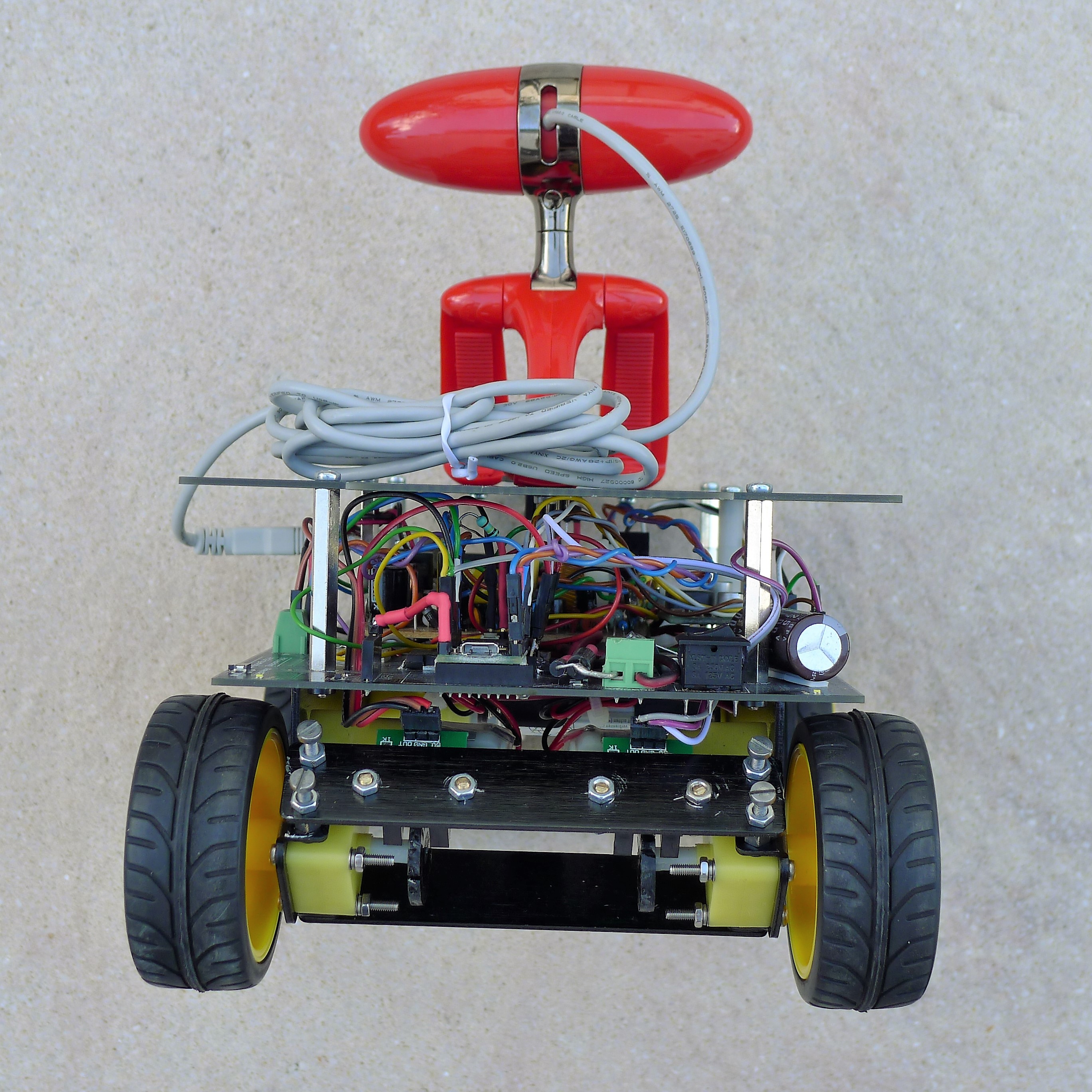
A few pictures of the complete robot assembly:
 |
 |
 |
 |
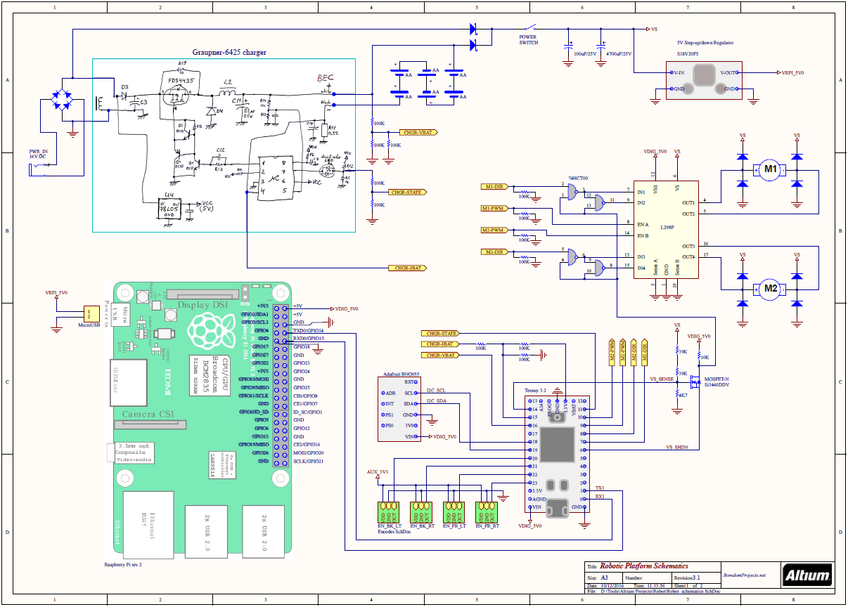
4.2.2. Schematics
Due to new sensors and cameras, the overall current consumption has increased quite a bit compared with first iteration of the platform. I noticed that during activity peaks, such as when driving and turning sharply, the batteries were not able to supply enough power and the supply to RPi would dip and cause it to reset. That's why I increased the number of batteries to six.
The circuitry of the optical encoders was improved by adding a small amount of histeresis and filtering (red components on the second page of schematics), in order to make the counting more reliable. I also disconnected LEDs to save some power.
4.2.3. Camera
Among many stereo cameras existing on the market, Minoru webcam is perhaps the cutest and achieves the best WAF (Wife Acceptance Factor). Although its specs are not very advanced, it has a single USB 2.0 port, which makes it easier to interface to RPi. The important thing to remember is that, through this single USB port, it exposes two independent camera interfaces, but the cameras themselves are unfortunately not synchronized in any way. This fact makes Minoru quite painful to work with. There are actually two timiming aspects to keep in mind:
- Each of the two cameras uses rolling shutter, as opposed to global. This means that during exposure each line of the frame is exposed and read out before the next one, as explained here. The resultant geometric distortions can break stereo disparity calculations when the robot is in motion or turning sharply. This becomes expecially critical when driving during sub-optimum, indoor lighting conditions when exposure time is longer.

- Start of exposure is not synchronized between the two cameras. This is also obviously a bad thing for stereo processing.
I have tried to work around these limitations with some success, but on the long run, the Minoru should be unfortunately replaced with another type of camera. Too bad, it looks so adorable! :-)
One more thing, because of the very small image sensor, the Minoru has a kind of tunnel vision, about 30 degrees wide. To improve the situation, I've replaced the lenses with something like this from Amazon. Unfortunately, the small sized sensor still did not allow to achieve anything more than about 60 degrees. This is far from optimum for navigation purposes.

4.3. Software
4.3.1. The OS
The choice of operating system for RPi was not simple. There are various flavors of linux that can run on Raspberry more or less stably. At the end, I settled on Ubuntu server 16.04 LTS mainly because it is the OS of choice for running ROS (Robot Operating System) framework. For graphical display management I use lightweight Openbox.
4.3.2. Communication
I have experimented with various methods of passing information between master RPi and slave Teensy. I started with I2C for the physical layer, but at the end settled on UART for its simplicity and low overhead. For communication I initially tried RH_Serial driver from Radiohead, but I found it to be somewhat limited and prone to framing errors.
Then I experimented with rosserial driver to package and transport ROS messages between the two processors. It worked for a while, until I started hitting the limitation of serial port, since ROS messages can be quite bulky and rosserial overhead is significant.
Finally I discovered communication library PacketSerial, which uses COBS algorithm to deal with framing errors. I extended this library to support flexible message payload and CRC error checking. I called it MessageSerial. On the RPi end, a small ROS node written in C++ and called base_serial performs the translation between MessageSerial packets and native ROS messages.
4.3.3. Stereo Processing
I was inspired by work of Bob Mottram who created a wrapper library around V4L2 utilities to simplify and streamline interface to a web cam under Linux. He also created a nice utility called v4l2stereo to specifically address stereo calibration and 3D reconstruction using Minoru camera.
The library was originally created targeting Intel architecture utilizing SSE instructions. To make it run on Raspberry, Ralph Campbell modified the code to remove dependency on SSE. In addition, I incorporated the changes by Edilson de Aguiar to add OpenMP optimizations. The resultant library can be found here: v4l2stereo_no_sse
In order to integrate this stereo library into ROS, I created a C++ node called minorucam, which can be tweaked using various parameters in camera.launch file. The node is capable of generating raw (left) image, disparity image, point cloud and laser scan types of output. Of course, for navigation, only laser scan is actually usefull. Normally, the minorucam node is capable of outputting about three laser scans every second. Not bad for Raspberry Pi, I think!
To battle the distortion created by rolling shutter, I added a parameter exposure to the camera processing node that optionally disables automatic exposure. This way, a maximum possible processing speed can be ensured to reduce the effect of motion smearing. Still, reasonable results could only be achieved during well lit, daylight conditions.
In addition, in order to minimize stereo correspondence search to absolute minimum and not to over-exert poor little RPi, I added an ability to limit vertical height of active view to 100 pixels (configurable by parameter height).
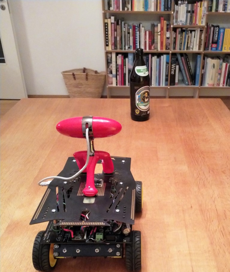
To illustrate stereo processing capability of the robot, I've set up a scene where the robot was staring at a beer bottle sitting on a table against a background of book cases:
The following video illustrates what robot was actually seeing, in RViz:
As you can see, the raw images are sized 640 x 100 pixels. The resultant disparity image looks pretty good, expecially for nearby objects. As the distance increases, though, the measurement errors become quite large, which can be seen from somewhat jumpy PointCloud. Althought the simulated Laser Scan line was produced by averaging vertical points at each angle, still, when the point cloud is disabled, one can see just how wavy the laser scan line is.
Also, I couldn't figure out why laser scan is not forming a straight line, but is somewhat bent outwards. Must be a bug in the calculations somewhere.
4.3.3.1. Error Analysis
When the robot is stationary, the stereo correspondence can be detected quite reliably. The problems start when the robot is in motion. Due to unsynchronized cameras, sometimes the laser scan could not be generated at all. This is especially true for twists and turns, when the scene in the view is changing rapidly, such as during rotate-recovery escape behaviour used in ROS' navigation stack. In some situations the robot would turn in-place for ever, unable to register any laser scan at all!
Considering a frame rate of 30 f/s and a typical in-place rotation of 0.4 rad/s (23 deg/s), in the worst case, there could be up to 9.3 pixel shift error between left and right pictures. In other words, due to unsynchronized cameras, the same point can move 9 pixels from the time of capturing right image to the time of capturing left image. This is not considering disparity, but the action of turning alone.
| frame rate | R | 30 | f/s |
| turning speed | θ | 0.4 | rad/s |
| image shift angle | α | 0.0133 | rad |
| image shift pixels | s | 9.3335 | pixels |
Now, the above 9-pixel shift can be added to the disparity and the resultant distance uncertanty can be estimated.
The following calculation illustrates worst case error in distance measurements due to unsynchronized cameras vs. various depths during a typical in-place rotation.
| Depth | Disparity | 9.3-pixel shift depth error | |||
| [mm] | [pix] | [+mm] | [-mm] | [+%] | [-%] |
| 100 | 420 | 2.2 | 2.3 | 2.2% | 2.3% |
| 1000 | 42 | 181.8 | 285.7 | 18.2% | 28.6% |
| 3000 | 14 | 1200.0 | 6000.3 | 40.0% | 200.0% |
| 5000 | 8.4 | 2631.6 | -49993.3 | 52.6% | -999.9% |
As you can see, recognition of nearby objects is not a problem. There is only a few percent added measurement error considering objects a few cm away.
However, as the distance increases, the error grows rapidly. For objects 1 m away, the error is 20-30% and for objects 3 or more meters away, the error becomes quite unmanageable!
The above calculations are here: camera-synch-error.xls
To try to mitigate the above problems I've done two things:
- Modified the rotate-recovery plug-in to periodically pause the rotation (every 30 degrees for 1 sec), to allow robot to get a good picture of the world.
- Added an optional functionality to minorucam node to prevent generating laser scan if current rotation rate exceeds certain amount. This is controled through some parameters in camera.launch file.
Of course, the above is just a band-aid solution. The real fix would be to replace Minoru with a properly synchronized stereo camera system.
4.3.4. Navigation
To navigate in space one normally needs a map. Unfortunately, my attempts to build a map using SLAM algorithms provided by ROS were not successful. The uncertainty of the depth measurements was too great, especially at some distances. As a result, the robot couldn't build reliable enough picture of distant walls and objects and couldn't close the loops. So, at the end, I manually made a map and imported it into ROS as a calibrated picture.
Due to the same reasons, I couldn't get AMCL (part of ROS navigation stack) to function reliable enough. It got periodically confused when the shape of distant objects returned by laser scan didn't match my map, or when a false match was detected and the robot position suddenly became way off.
Nevertheless, one can see from the video that basic nearby object detection and collision avoidance is working. I'm very happy about that! :-)
4.3.5. Code
The ROS workspace for the Master (Raspberry Pi) is on github here:
https://github.com/icboredman/cherokey_ws/tree/af129a71ac3f16206897c94bc58387545cf9569d
and the Arduino code for the Slave (teensy 3.2) is here:
https://github.com/icboredman/cherokey_slave
5. Conclusions and next steps
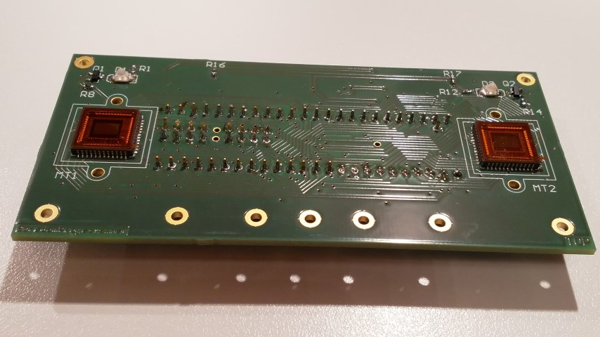
So far I have been able to achieve only limited autonomous navigation capability. It is currently prone to errors and the results depend a lot on lighting conditions. The SLAM algorithm doesn't work at all because the distance measurements are not accurate enough. Obviously, the robot has problems finding its way due to limitations of Minoru camera. It's a shame, though, cause it's so damn cute! Still, that's why I have already started working on an improved version of stereo sensor based on MT9V034 modules. These are large, very sensitive imaging arrays with global shutter and synchronization capability! Below is a little preview, but detailed description will be subject of another blog post. :-)
 |
 |