1. Purpose
- Attempt to implement robot indoor navigation
- Automatically guide Roomba from room to room
- Eliminate need for lighthouses during cleaning cycle
- Experiment with computer vision algorithms
- Experiment with vision-based feedback and control system
2. Components
- iRobot Roomba 880
- Raspberry Pi 2 with NoIR camera
- OpenCV computer vision library
- Arduino PRO MINI (5V)
- XL4432-SMT 433MHz Transceiver
3. Results - on YouTube
4. Progress Report
4.1. Intro
Building upon my first experiments with iRobot Roomba documented here: Controlling Roomba with Arduino, I decided this time to go further, to see if I can make Roomba to find its way from one room to another, all on its own. The problem is I was getting a bit fed up with a need to put up lighthouses in doorways before every cleaning cycle. If I forget to do this, Roomba gets confused, stuck somewhere in another room, unable to find its way back to the room where its charging base is located.
Obviously, navigation between rooms requires some sort of location awareness, which my Roomba by itself does not have. Initially I was thinking in the direction of navigation and mapping sensors for Roomba, perhaps radio or IR ranging, or maybe something like what was already implemented in the latest Roomba 980 series. Seemed a bit too complicated for me to pack such device on top of the robot. So, at the end, I opted to offload this functionality to an external device, which would keep track of Roomba's location and send the guiding commands to it over the radio.
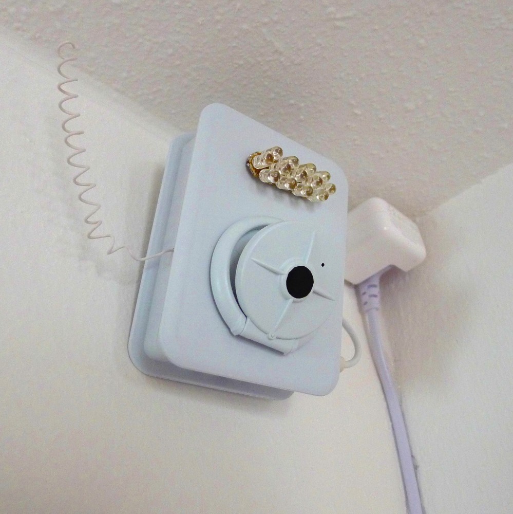
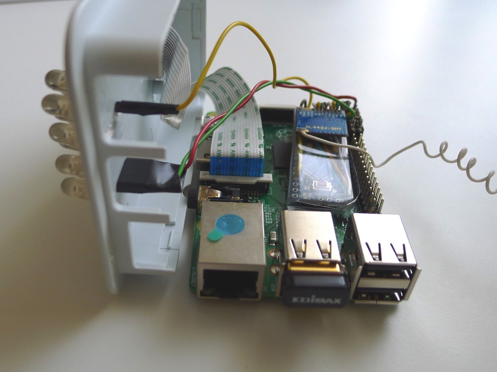
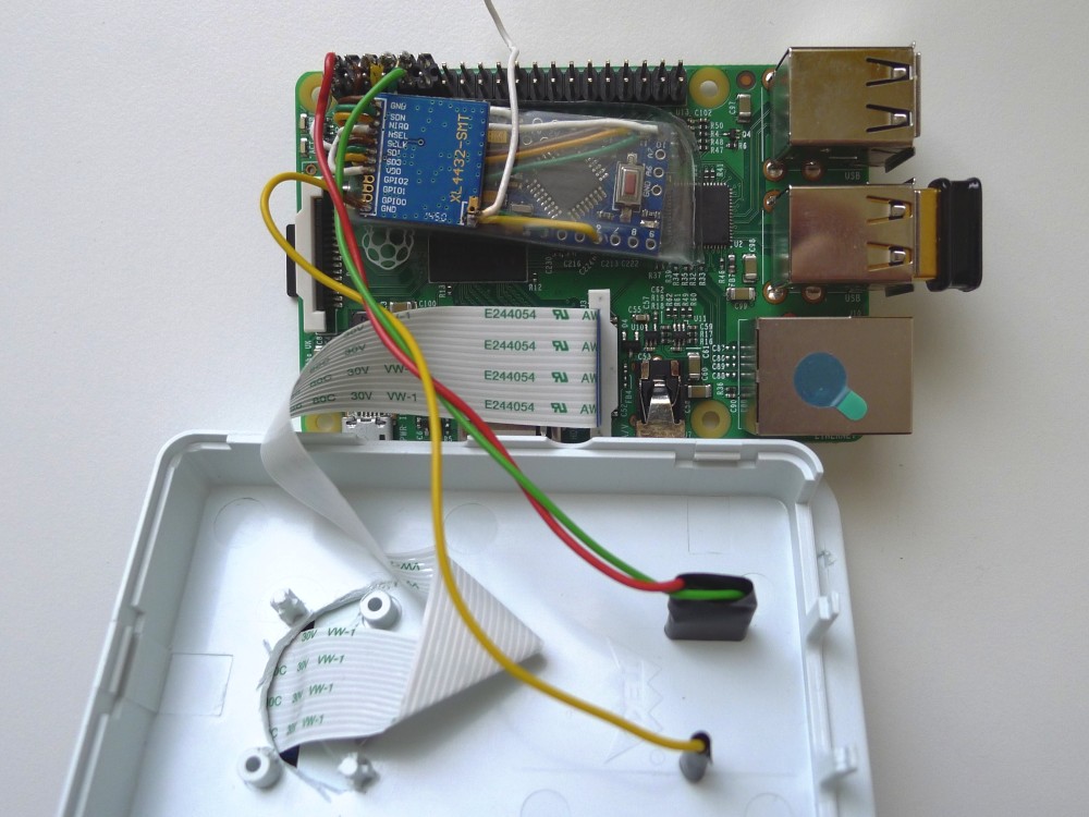
This is how Owl was born. It is a Raspberry Pi with a camera and a XL4432 transceiver, mounted high in a corner of a hallway, overlooking the floor area between one room and another. It is meant to continuously look down, trying to find Roomba in its field of view. As soon as it detects the robot, it would take over its controls and would start adjusting its course, in order to guide it from room to room. It would also keep track of how long Roomba spent in the first room and would only allow it to cross over when it was time to do so. At the end of the cleaning cycle, Owl would guide the robot back to the room where its base is located. Owl should also have the ability to monitor Roomba's battery state and current activity. This should not be a problem, since detailed sensor information is available through robot's communication interface.
Anyway, these were my plans, quite ambitious, ha? So far, I have gone only a part of the way.
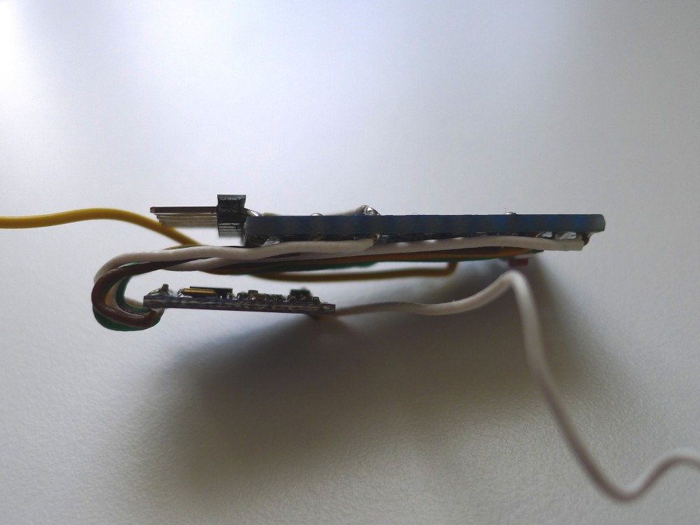
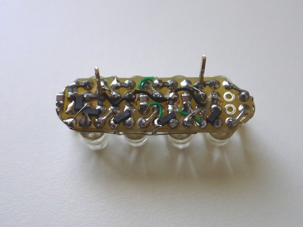
4.2. Hardware
The slave controller sitting inside Roomba was already documented here:
Controlling iRobot Roomba with Arduino
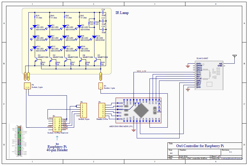
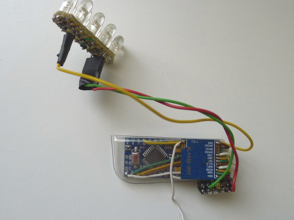
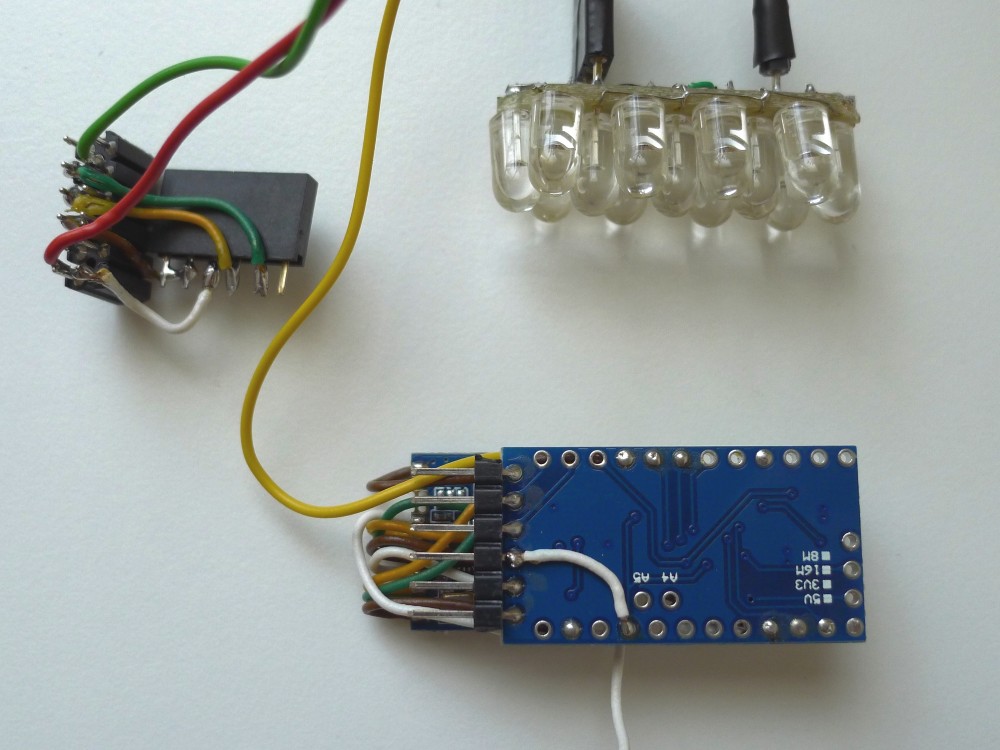
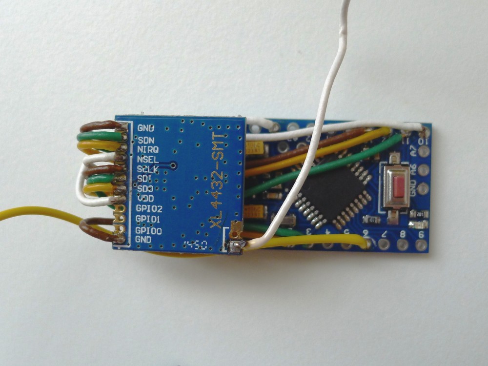
And here's the schematics of the master controller:
and some pictures of it together with Raspberry Pi:
 |
 |
 |
 |
 |
 |
 |
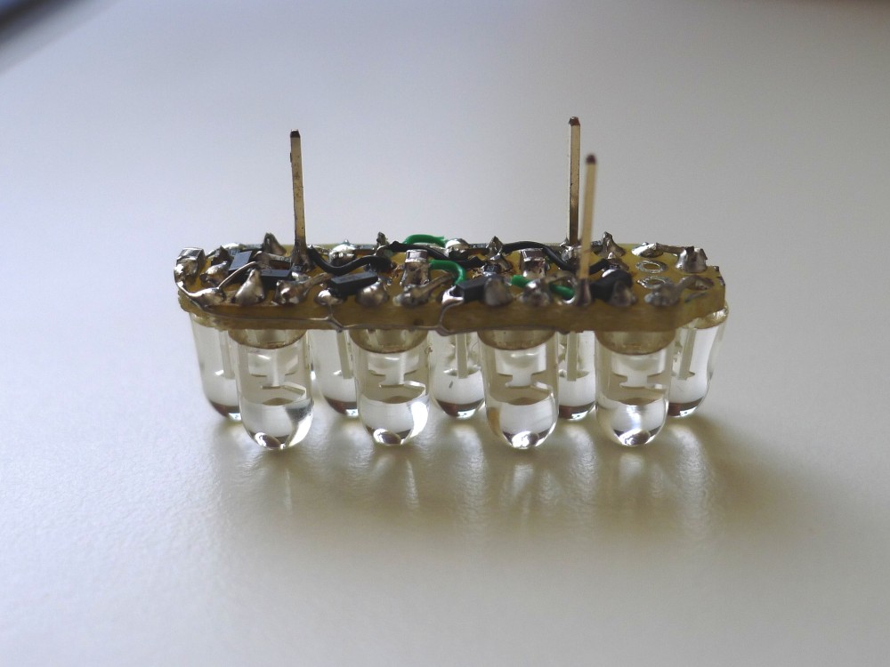 |
I used NoIR camera with a piece of exposed negative glued in front of the lens. This was done with hope to detect Roomba in low light conditions.
The 13-LED IR lamp was meant to provide invisible illumination. Turned out, the lamp was not bright enough or it was located too far away to make a noticeable difference. Something to think about for the future.
4.3. Software
4.3.1. Application layer - Raspberry Pi
I have to say that my knowledge of computer vision techniques is very very limited. The methods used to make this work will undoubtedly appear simplistic and amateur. But that was exactly my goal - to learn by experimenting.
To install OpenCV 3.x on Raspbian Jessie, I followed this excellent tutorial by Adrian Rosebrock.
Code was written in C++ referencing OpenCV version 3.1.x. and can be found on GitHub here:
https://github.com/icboredman/Owl/tree/master
The main function is located in Owl.cpp. For every new video frame, the procedure is:
- locate robot within the frame
- calculate its current motion vector
- calculate turn angle to direct it towards next point in the path
- transmit drive/turn command to the robot
- check if the next point in the path has been reached, and if yes - set up next point to go to
I used Perspective Transform to make it easier to calculate robot coordinates and motion vectors. This is how the scene looks from Owl's point of view before and after perspective correction. Notice how the floor tiles look perfectly square in the right picture:
|
Normal view
|
After perspective correction
|

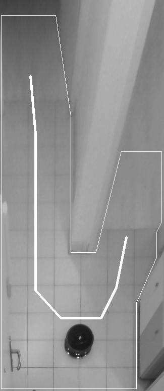
The search area is defined using a contour, marked in the above picture by thin while lines. Search algorithms try to locate robot within this area.
The thick white lines mark the path Roomba should follow around the wall, in order to go from one room to another.
The small white dots are actually Roomba's infrared proximity sensors.
I tried to use a combination of several methods to locate Roomba in the image. First method uses HoughCircles algorithm. Its parameters are tuned to the size of the round dark shape of the robot, in order to detect center of its circle. This processing is wrapped inside FindShapeCircles() function. Second method uses SimpleBlobDetector method. There are actually two variants of functions that use this method. One is tuned to the small white dots created by LEDs of Roomba's IR sensors and the other is tuned to a large dark blob representing the shape of Roomba itself. Thus I have two functions: FindSmallBlobs() and FindLargeBlobs(). The second one was, unfortunately, not very reliable, giving a lot of false detections, so I eventually removed it.
The detected possible locations are qualified according to mutual grouping and position within the image. At the end, the most probable center of Roomba is calculated by minEnclosingCircle().
Lately I learned that this quite simplistic approach can and should be complemented with or replaced by such techniques as background/foreground segmentation and motion tracking. This is something for me to study in the future.
4.3.2. Transport layer - Arduino
All drive commands, sensors information, status monitoring and mode switching is implemented according to iRobot specification that can be found here: http://irobot.lv/uploaded_files/File/iRobot_Roomba_500_Open_Interface_Spec.pdf.
The Arduino Pro Mini, which is attached to Raspberry Pi, is responsible for communication with Roomba using XL4432 433MHz module. The Mini also controls the IR lamp. Source code is on GitHub here:
https://github.com/icboredman/Owl/tree/arduino_roomba_master
And the code for the Mini riding the Roomba is here:
https://github.com/icboredman/Owl/tree/arduino_roomba_slave
It is possible, despite Owl's very sharp vision, for Roomba to hit a wall once in a while. To prevent damage to motors, I implemented local bump sensor processing in the slave Arduino. When a collision is detected, Roomba executes a procedure to stop, back up and turn 90°, while ignoring remote commands momentarily. After the maneuver is finished, it resumes listening to remote control.
4.4. One more video
This time Owl is directing Roomba to follow the path in reverse:
In the right side of the video, the small white circle marks the current detected location of Roomba. The small gray circle marks the next destination point on the path robot should follow. The two black lines with arrows indicate current motion vector (from last location to the current location) and the new motion vector (towards the next destination).
Notice how in the beginning Owl lost the robot momentarily, because it was located near the edge of the search area. This caused Roomba to stumble and stop for a second. Eventually Owl was able to detect robot's shape again and reestablished its control.
5. Conclusions
At the end, I did not manage to completely achieve my goal - to monitor and control Roomba's cleaning cycles and augment them with automatic room-to-room navigation. However, I did manage to teach Owl to recognize Roomba and to command it to go around the corner, as if on autopilot! After that, I lost interest and decided to move on to more interesting things, also involving computer vision...