1. The Purpose (Mission)
- To integrate various environmental and security sensors into my Home Energy Monitoing System
- Outdoor temperature
- Indoor temperature
- Humidity
- Atmospheric pressure
- Door/window security sensors
2. Components
- Concept based on OpenEnergyMonitor project
- Hardware: JeeNodeUSB, Arduino-Pro-Mini, RFM12B, BMP085, DS18B20
- Software: Arduino IDE, EmonLib and RFM12B library by LowPowerLab
3. Progress Report
3.1. Outdoor Temperature Sensor
Naturally, the main feature of such device had to be autonomous, wireless operation. This means battery powered operation, low current consumption and wireless data transmission.
RFM12B transceiver was an obvious choice, since I already used them in other parts of my Energy Monitor.
For the temperature sensor itself, I chose DS18B20 made by Maxim. They were easy to use and Arduino library for it was readily available.
Finally, for the processor, I decided to use Arduino Pro Mini board, made by Sparkfun, for its simplicity, which is what's needed for battery powered operation. The board detailed description is here: https://www.sparkfun.com/products/11114
|
|
|
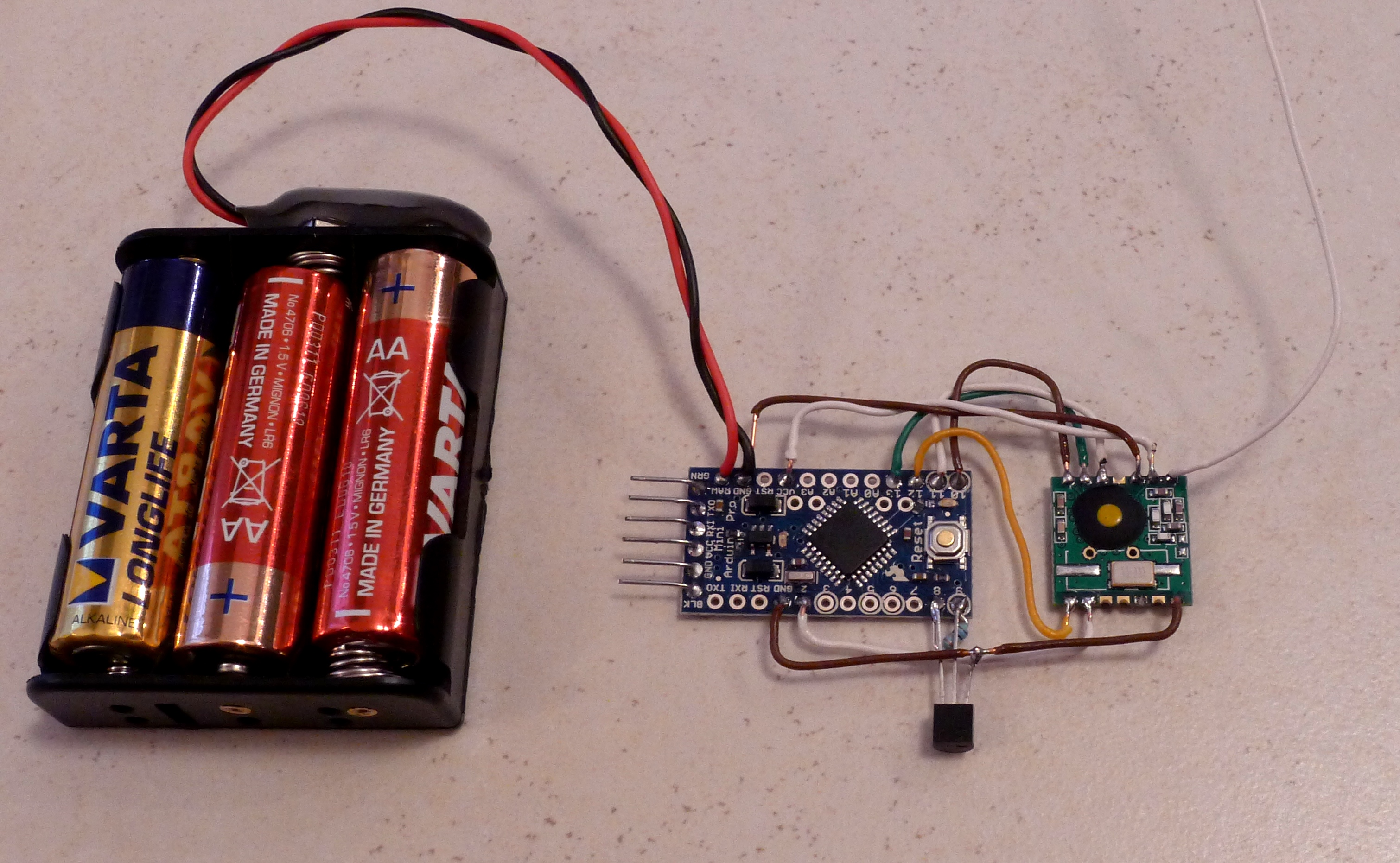
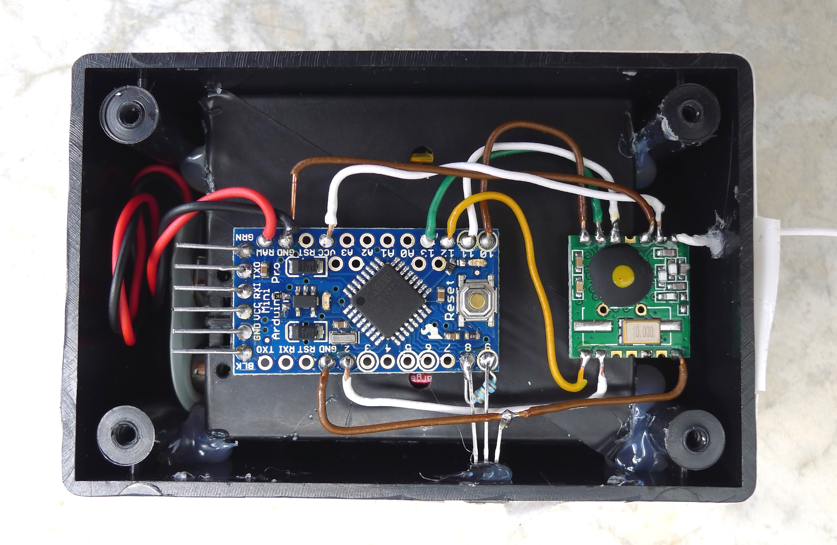
All the above components are in sleep more for most of the time, only waking up for short periods to take a temperature reading and transmit data out.
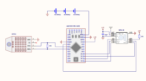
Here's the schematic diagram of the sensor:
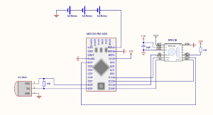
I chose to use 3 AA batteries to power the unit through RAW power input. The on board LDO has a low quiescent current, so during sleep times, the system would draw only about 100µA. And during wake times, the current would be limited by the temperature sensor + radio, anyways. I calculated that the battery should last about 5-6 months. We'll see...
UPDATE (Dec. 2014): The batteries are finally dead. After almost 8 months! I'd say it's pretty damn good! :)
And, of course, here's the Arduino sketch: Sensor_Outside.ino
Part of the sketch is a code enabling low battery threshold on RFM12B and reporting it back to the base together with temperature reading.
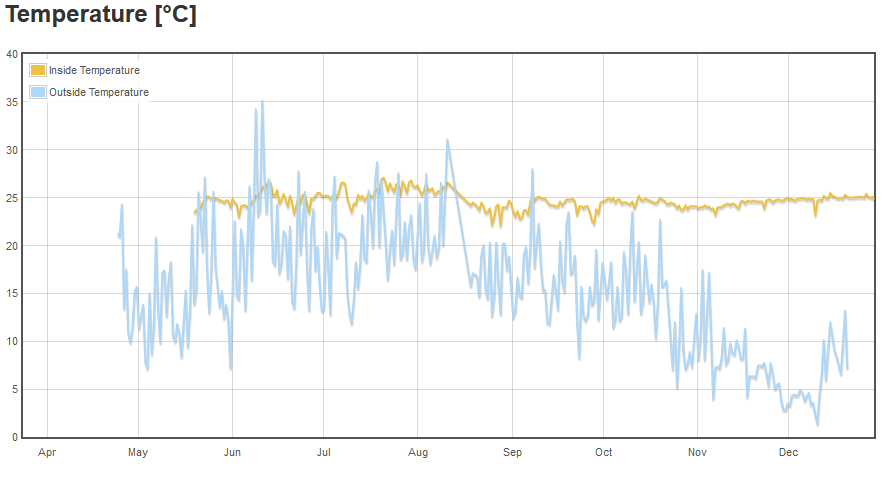
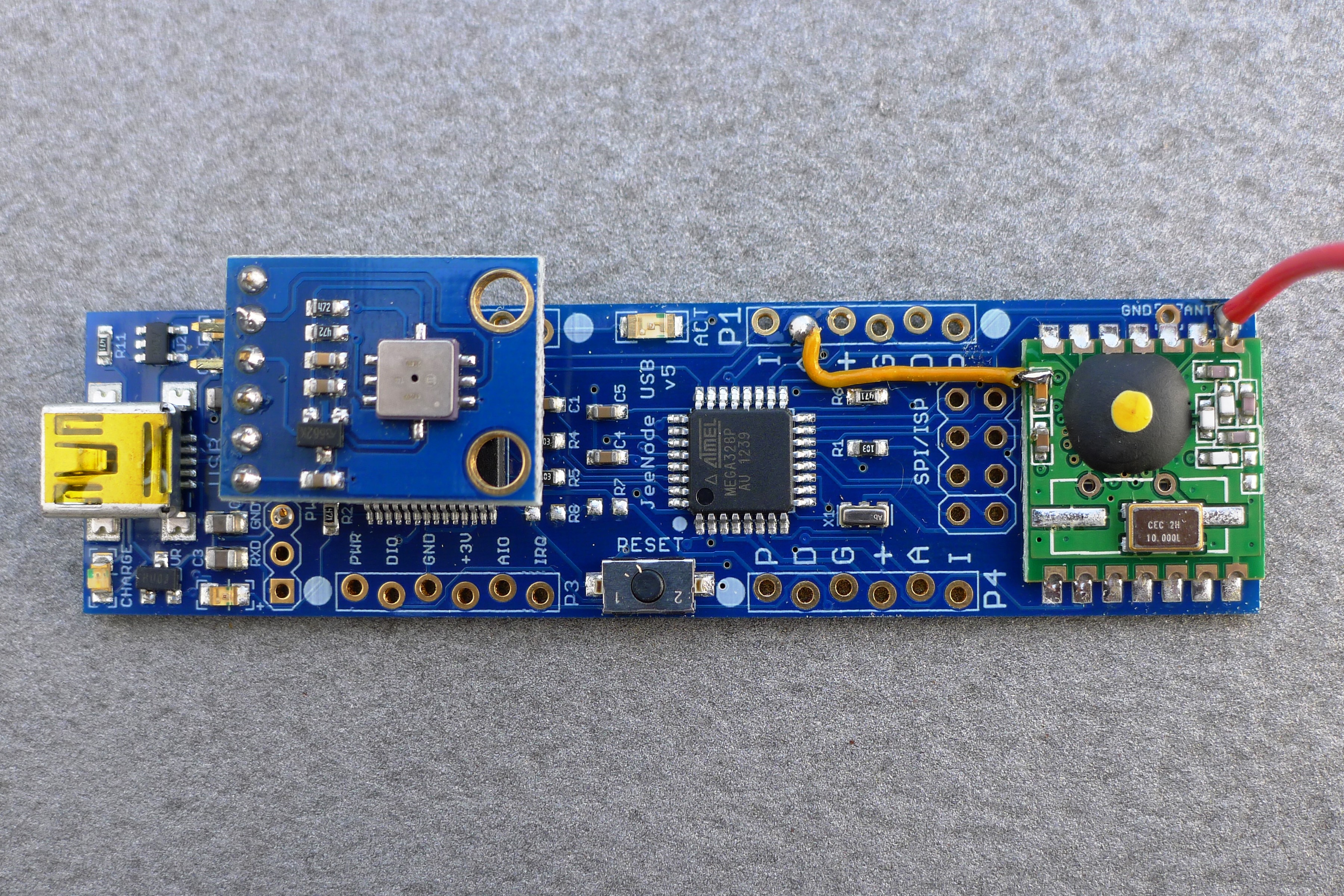
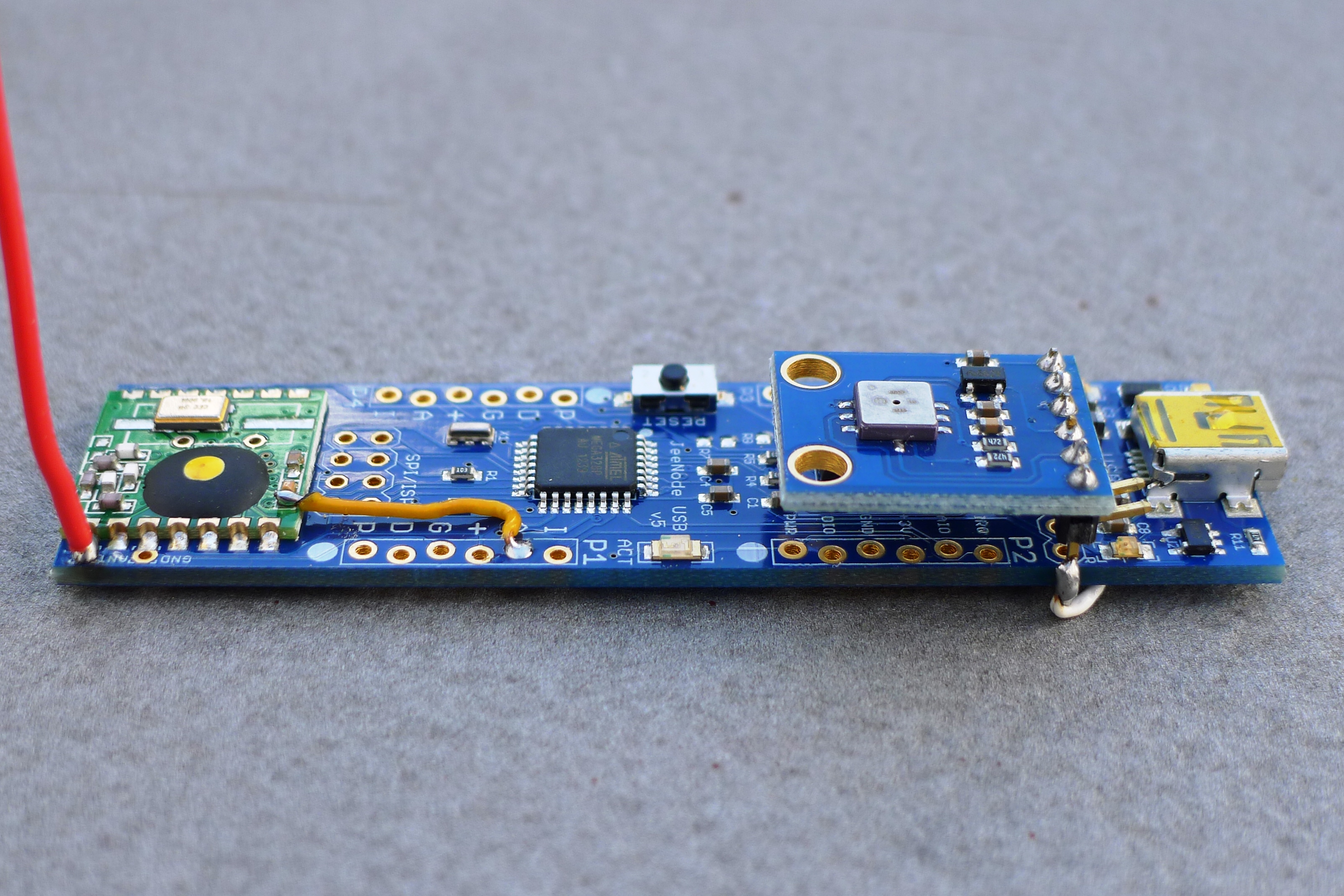
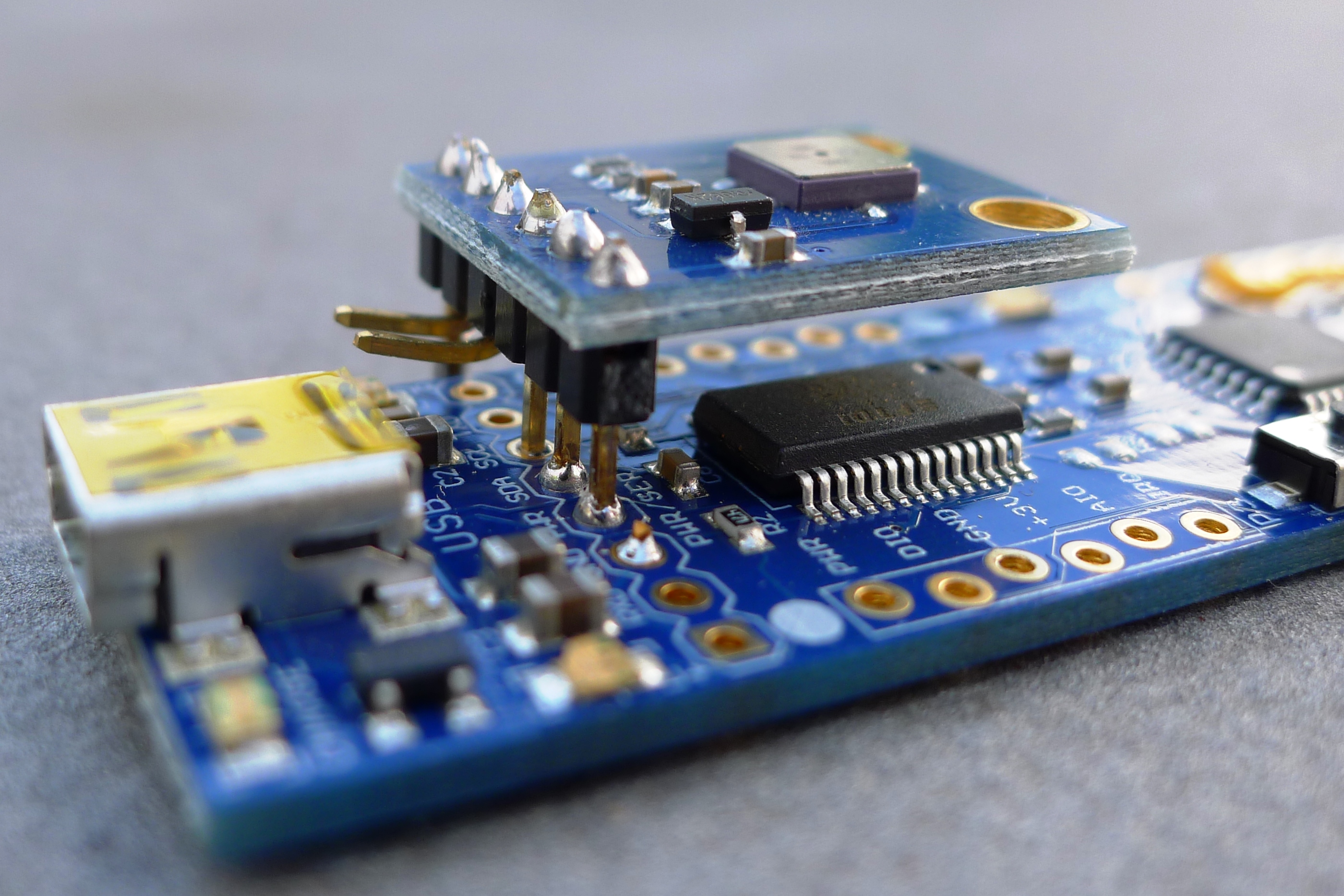
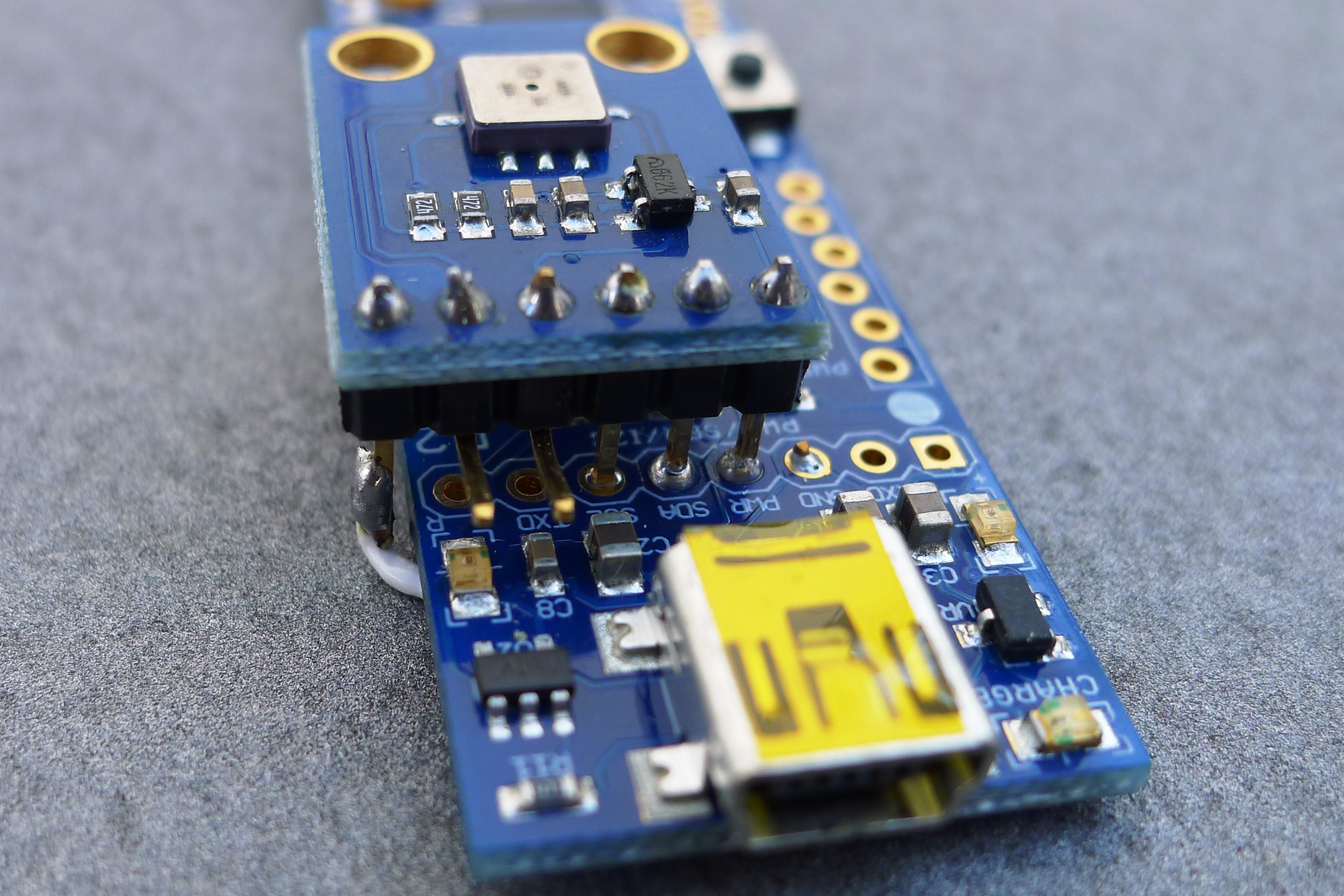
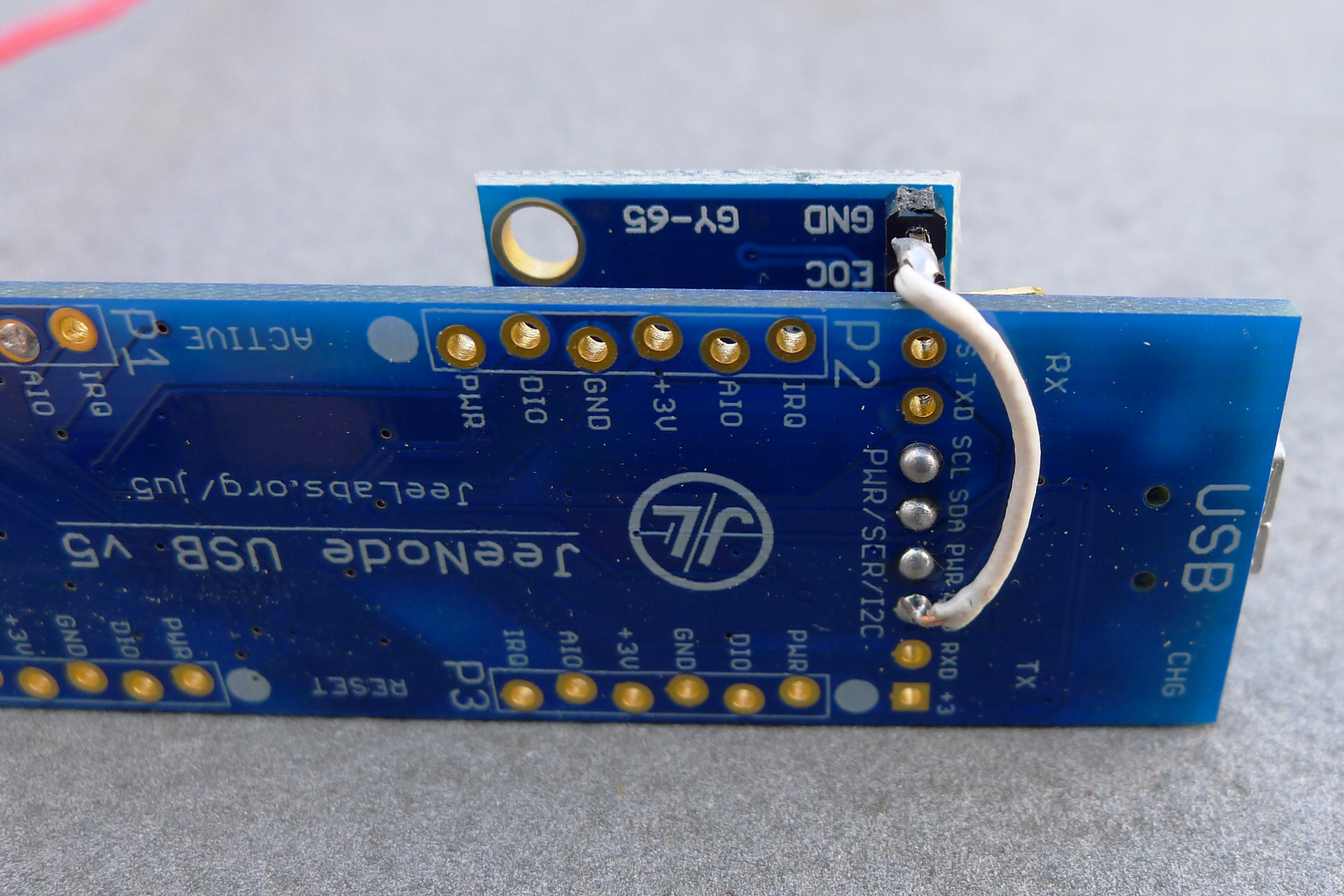
3.2. Indoor Temperature and Pressure Sensor
Since I already used JeeNodeUSB with RFM12B as a main data collection interface, it seemed easiest just to add the additional indoor sensor directly to it. The BMP085 from Adafruit was perfect for that, providing both Pressure and Temperature readings in one package.
 |
 |
 |
 |
 |
Interesting thing that I discovered, which was new to me, is that absolute atmospheric pressure reading produced by the sensor needs to be converted to pressure at sea level. This is what is used by all weather reports. That means the following calculation is performed on the receiving end (by EmonCMS input processing engine):
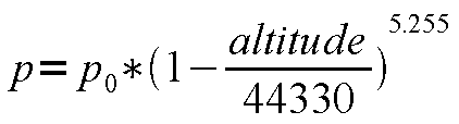
For excellent explanation of this topic see this Sparkfun tutorial.
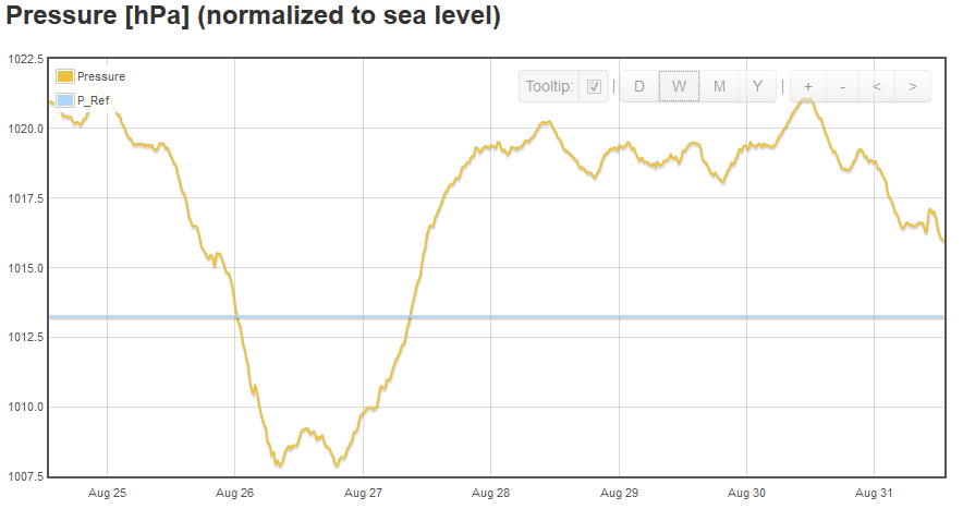
In addition, I set up a dummy pressure input that always shows sea level pressure, to be used as reference. This makes it easy to judge high or low pressure tendencies.
This dummy pressure input is generated inside my RaspberryPi server running EmonCMS. I simply set up a cron job with this command to run a script every hour:
0 * * * * /home/pi/log_reference_pressure.sh
and the script itself is very simple:
curl -k -u "username:password" "https://127.0.0.1/emoncms/input/post.json?node=1&csv=1013.25&apikey=emonApiKey"
where username, password and emonApiKey must be replaced with actual parameters from your box, and 1013.25 is average sea level pressure in hPa.
3.3. Indoor Humidity and Temperature Sensor
This one is very similar to Outdoor Temperature Sensor, except here I used DHT22 - all-in-one humidity and temperature measurement device. The controller is again Arduino Pro Mini, powered by three AA batteries. And the radio is RFM12B.
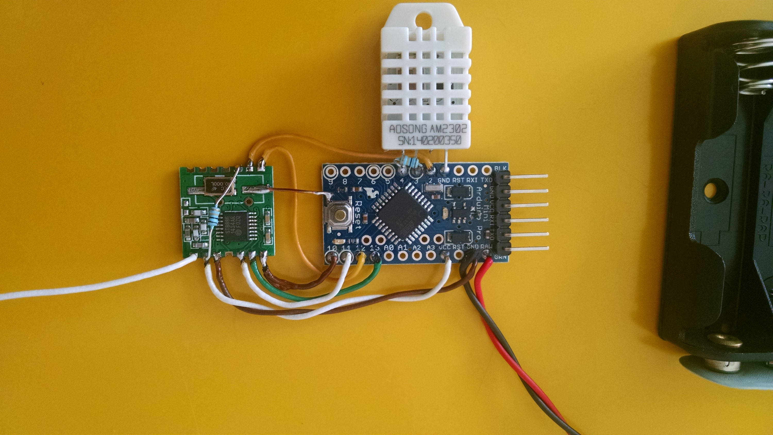
I found that when idle, the DHT sensor draws about 1mA, which is too much for battery powered system. Therefore, I connected its VCC line to a digital output pin on Arduino, which is turned ON only during measurement time. However, to function properly, the power on DHT must be present and stable for more than 1 sec, before attempting to take readings.
I used DHT library made by Rob Tillaart (http://playground.arduino.cc/Main/DHTLib), however with one small modification - I commented out the very last two lines, which normally configure communication pin as OUTPUT and set it HIGH. The reason is, if this pin is driven HIGH and the power pin is driven LOW, there will be a useless current flow through the pull up resistor, connected between these two pins. Besides, if power supply to the sensor is cut off, there is no need to worry what state the comm pin is left in.
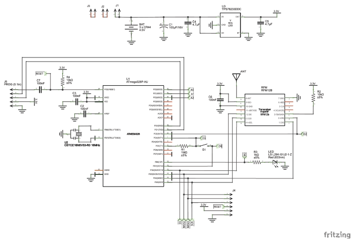
Here is the complete schematic diagram:
And here's the Arduino sketch: Sensor_Inside.ino
3.4. Door/Window Security Sensors
Although these do not strictly fall under category of environmental, but rather security related sensors, still I decided to include them in this post.
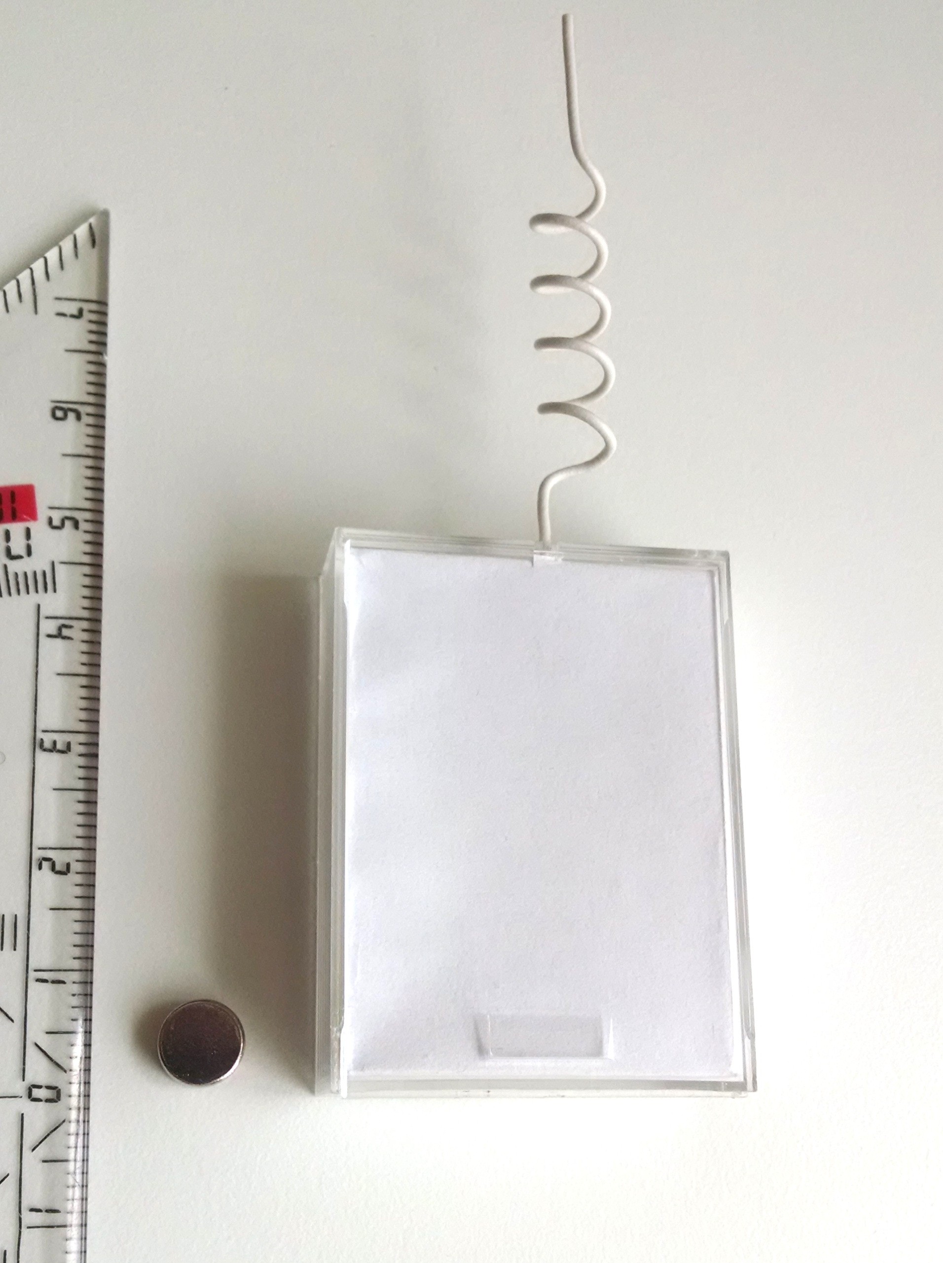
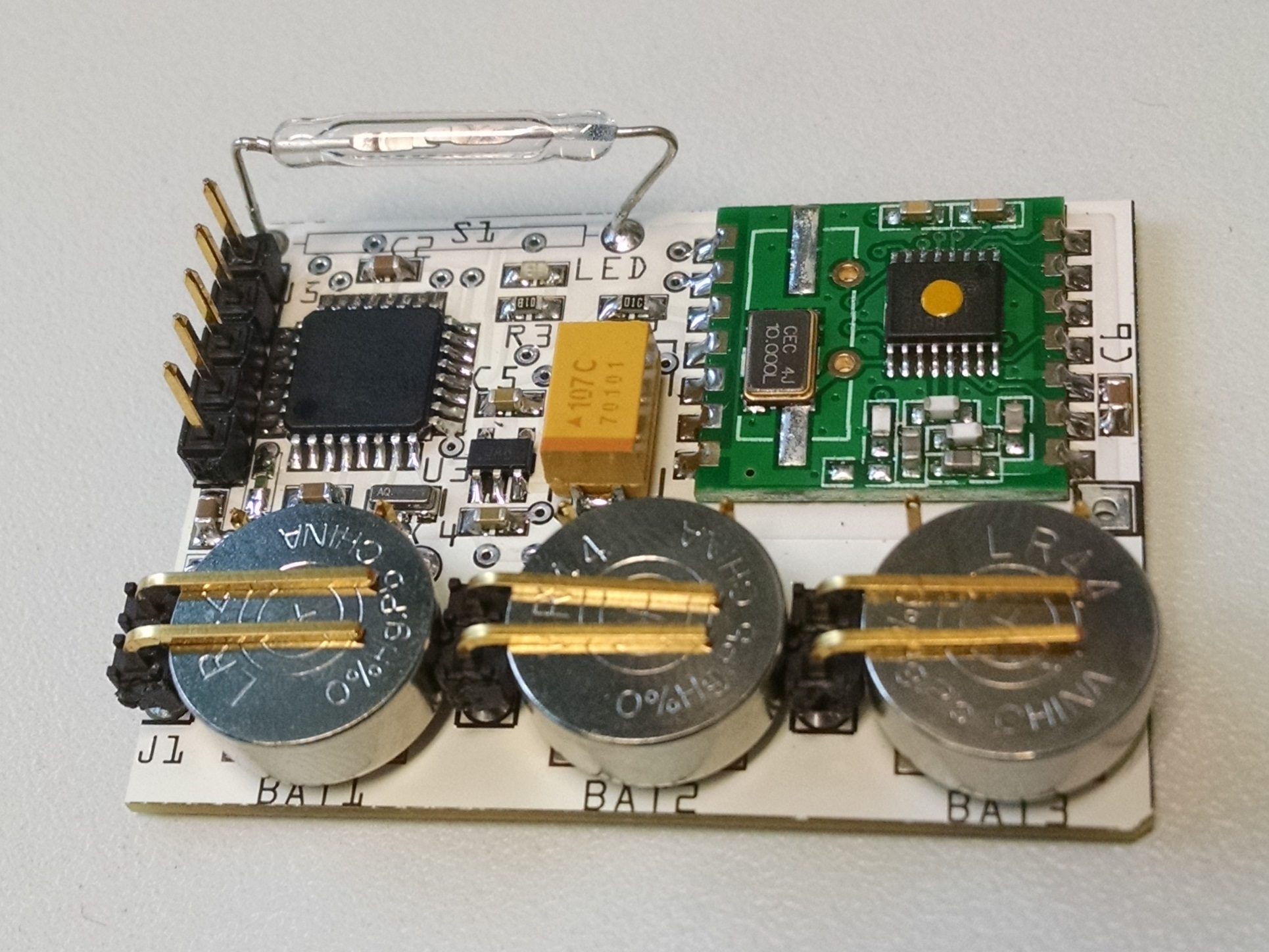
Basically, the sensors contain a Reed switch, ATmega328P controller and RFM12B radio. All of this is powered by 3 x LR44 coin cell batteries. Since I planned to have several of these devices throughout the house, I decided to make a proper PCB, designed and ordered through Fritzing.org. Here's the link to the design:
Fritzing Wireless Door/Window sensor
and schematic diagram:
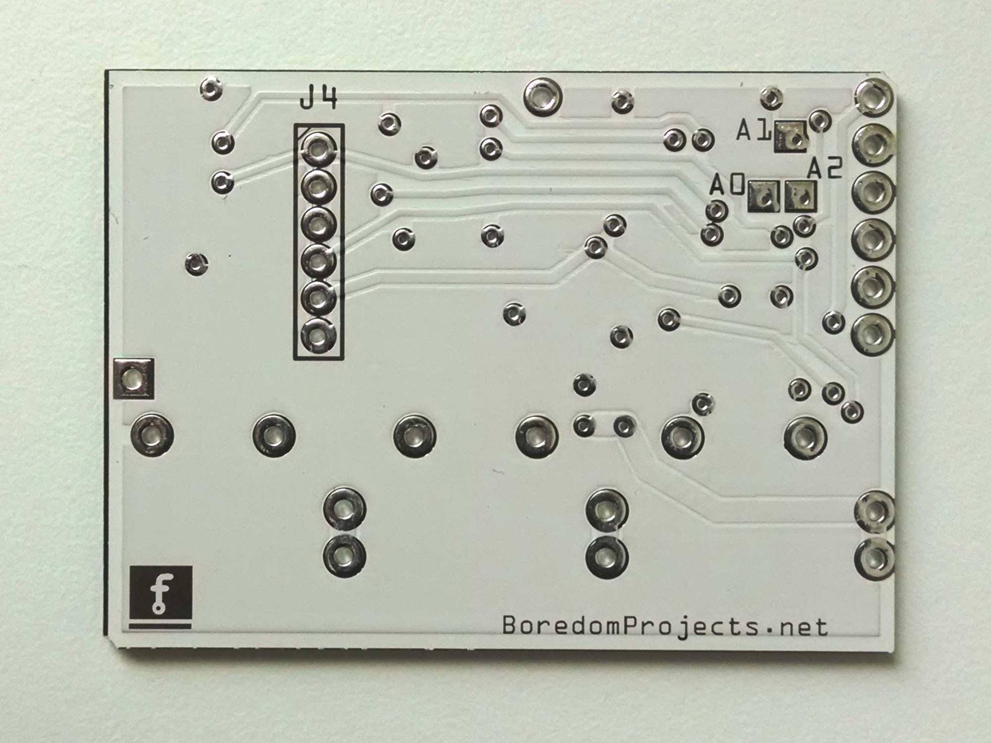
and some pictures:
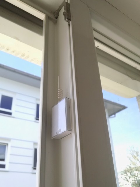 |
 |
 |
 |
 |
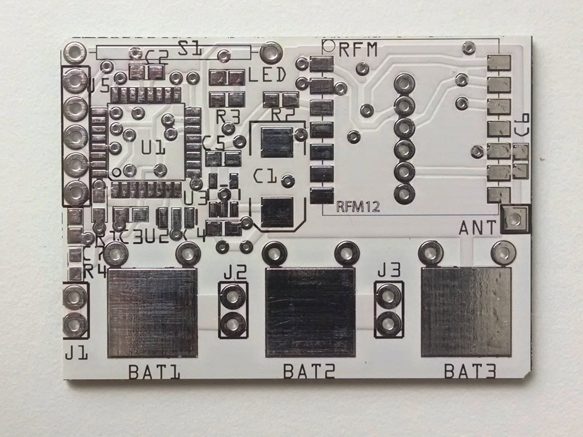 |
I must say, quality of Fritzing PCB manufacturing is pretty good. Although I had to pay about 70€ for 10 pieces. Not the cheapest service, I guess.
In order to make the sensor as small as possible, I had to use improvised battery holder connectors. I couldn't find any ready made connectors, surface mount or through-hole, which could fit three batteries into the small plastic case. These header pins are not so easy to solder, but they work pretty damn good!
Magnets and Reed switches I bought from Pollin.de: Magnet 7x3mm and Reedkontakt PRK-2,5x16
Connector J4 (2mm pitch) is used as ISP port, to program Arduino bootloader into ATmega328. This tutorial has detailed procedure on how to do that. Once the bootloader is in, all the programming and reprogramming is done through J5 connector (0.1" pitch) in a normal way through Arduino software and a compatible Serial-to-USB converter.
To conserve battery power, the device is in sleep mode for most of the time. The reed switch is attached to hardware interrupt pin, which wakes up the micro, as soon as a change of state is detected. Tree packets of new state data are transmitted out (for redundancy) and device enters sleep mode again.
In addition to state change driven transmissions, the program also enables watch dog timer, set for approximately 1 hour. So, if nothing is happening, the sensor will wake itself up every hour to send out its current state. This is done to monitor sensor's health status from the central hub, in order to detect dead battery, for example.
Here's Arduino sketch for this sensor: Sensor_Door.ino
Few notes on power consumption:
Brown Out Detector has a big influence on power consumption during sleep mode. The above code includes a way to turn it off.
Since external interrupt pin only works as a low level triggering, the direction of the pull resistor (R1) is flipped from GND to VCC. At the same time, the opposite pin of reed switch is flipped from VCC to GND. This is done to ensure that no matter whether the switch is open or closed, the next state change will always produce low level hardware interrupt. One side effect is when reed is magnetized (door is closed) there is a small current flow through R1 (acting as pull-down in this case), resulting in a few additional µA of current draw.
Measured power consumption from battery port (including LDO bias current):
- Sleeping - door opened ...... 13uA
- Sleeping - door closed ........ 16uA
- Active - preparing ........... 3mA (4msec)
- Active - transmitting ....... 25mA (3msec)
The active current consumption was measured by attaching a 6.8 Ohm resistor in series with supply and monitoring voltage across its terminals on a oscilloscope:
![]()
I estimate the batteries should last for about 8 months. Let's see...
---------
UPDATE (May 2017): The batteries finally started to die. That's about a year of battery life! :-)
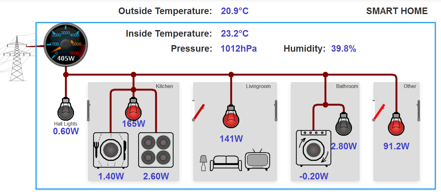
3.5. Dashboard for EmonCMS
Finally, with all these sensors, I was able to create this nice (i.m.o.) looking dashboard for my Home Energy Monitoring System:
By the way, to represent door/window state, I created a simple Door widget, by modifying led widget example. Here is the JavaScript code:
Comments
I would guess you have a wrong formula in Node processing in your EmonCMS. Mine looks like that:
Comparing the measurement of atmospheric pressure sensor with the official airport which is close to my city and there is little difference. The second factor 1.06563 how is it determined? Does it matter the altitude or other factors?
SparkFun website has an excellent explanation of this:
www.sparkfun.com/tutorials/253
Good luck!
In my second factor get 1.019386 at 170 meters altitude.
Good luck to you!
RSS feed for comments to this post